
Solid State Relay Basics: A Beginner's Explainer for Consumer Electronics Designers
A solid state relay (SSR) is an electronic switching device that opens and closes a load circuit using semiconductor output components instead of mechanical contacts. It accepts a control signal through an optically isolated input and performs the actual switching with no moving parts. For a consumer electronics designer, that single architectural difference is what makes the SSR worth understanding: no contact wear, no contact bounce, no audible click, and no arc at the switching point.
This explainer is written for designers meeting the category for the first time. It covers what an SSR is, how its internal signal path differs from a mechanical contact relay, where the technology fits inside a broader switch portfolio, and how to move from a conceptual understanding to a specification review. XURUI is used as the reference portfolio throughout, because its switch family contains both mechanical switching products and solid state relays, which makes the contrast concrete. XURUI is the brand of Zhejiang Xurui Electronic Co., Ltd., a Chinese manufacturer founded in 2002 that produces micro switches, limit switches, foot switches, toggle switches, reed switches, solid state relays, proximity switches and photoelectric switches.
The Problem: Every Mechanical Contact Eventually Wears
A conventional electromechanical relay does its job with metal. A coil pulls an armature, the armature drives a moving contact into a fixed contact, and current flows through that physical junction. The architecture is proven and inexpensive, but it carries a set of design constraints that follow directly from the physics of metal touching metal.
The first constraint is wear. Contacts erode slightly with every operation, and the erosion accelerates when the load is inductive or when inrush current is present. The second is noise: the armature produces an audible click each time it actuates, which becomes a problem in products that sit next to a user, such as appliances, office equipment, and home automation modules. The third is contact bounce, a brief unstable period during which the contact makes and breaks several times before settling. The fourth is arcing, which occurs when a contact interrupts a live circuit and can degrade both the contact surface and the surrounding material over time.
None of these issues makes an electromechanical relay the wrong choice. They simply define where it stops being the best fit. The designer's real question is not "which relay is better" but "which switching mechanism matches this load, this duty cycle, and this acoustic environment." Answering that question requires knowing that the semiconductor alternative exists and understanding what it does differently.
Industry Background: Where the Solid State Relay Sits in a Switch Portfolio
Switching components form a spectrum rather than a single category. At one end sit purely mechanical devices whose state changes only when an actuator physically moves them. At the other end sit semiconductor devices whose state changes when an electrical signal is applied. Most consumer electronic designs use components from several points along that spectrum at once.
Micro switches and limit switches are mechanical position-sensing devices. A micro switch is a small, snap-action switch actuated by a plunger or lever; a limit switch packages similar contact mechanics inside a housing designed for machine position detection. Safety interlock switches, foot switches and elevator door switches are application-specific mechanical switch families. Reed switches use sealed, magnetically actuated contacts with no external lever. Toggle switches are manually operated mechanical devices. A solid state relay sits apart from all of these: it is not actuated by a human hand or a machine cam, but by a low-power control signal, and it switches with no contact movement at all.
That distinction explains why a company that already supplies mechanical switches would also supply solid state relays. A design team building a product enclosure often needs a mechanical switch for user input, a position switch for a door or drawer, and a semiconductor device for switching the actual load. XURUI's portfolio covers all three roles, which is why the SSR appears alongside micro switches, limit switches, foot switches, toggle switches, reed switches, safety interlock switches and elevator door switches rather than replacing any of them.
What a Solid State Relay Actually Is
Three functional blocks define an SSR. The input block accepts the control signal and converts it into light. The isolation block, typically an optocoupler, transmits that light across a physical gap so that the control side and the load side share no electrical connection. The output block uses a semiconductor switch to open or close the load circuit in response to the isolated signal.
The defining property of an SSR is the absence of a mechanical contact. There is no armature, no spring, no moving blade and no metal-to-metal junction in the current path. Switching happens entirely within semiconductor material, which is why the device has a practically unlimited number of operations compared with a contact mechanism.
The optical isolation stage is what makes the architecture usable in real products. Because the control signal crosses the barrier as light, a low-voltage logic circuit can switch a much higher load voltage without a direct electrical path between them. This is the same principle that allows control electronics to remain electrically separated from the load side in a finished device.
What the SSR does not do is switch without loss. A semiconductor output dissipates a small amount of energy as heat during conduction, which means thermal design becomes part of the selection task. This is a genuine trade-off, not a footnote: the designer gives up contact mechanics and receives heat generation in return.
AC Output and DC Output Solid State Relays
The output stage determines which load types a given SSR can control, and the two families behave differently.
An AC solid state relay controls alternating current loads. Its output stage is built around a semiconductor pair that conducts in both directions, which is why an AC SSR can switch loads such as heaters, lamps, small AC motors and transformer-fed circuits. Within this family, the zero crossing solid state relay is a distinct variant: it waits until the AC waveform passes through zero before turning on, which reduces the electrical disturbance created at switch-on. A designer specifying a 240 V solid state relay or a 220 VAC solid state relay for a mains-fed heating element will usually be working within this AC, zero-crossing category.
A DC solid state relay controls direct current loads. Its output stage uses a unidirectional semiconductor switch, so it must be wired with correct polarity. The term "solid state relay DC to DC" describes the case where both the control side and the load side are direct current, while "DC to AC solid state relay" describes a device that accepts a direct current control signal but switches an alternating current load. Getting this pair right early prevents a polarity or load-type mismatch discovered only at prototype stage.
Some industrial variants extend the same architecture to three-phase loads, dual-channel configurations and adjustable output settings, and current ratings such as 25 A and 40 A are commonly discussed in procurement conversations. Those numbers belong to specific product data, and a designer should confirm them against the supplier's published datasheet rather than assume them from a category description.
Solid State Relay vs. Mechanical Contact Relay: What Actually Differs
The comparison below is architectural rather than commercial. It describes how the two switching mechanisms behave, so that a designer can decide which one belongs in a given circuit.
| Design dimension | Solid state relay (SSR) | Mechanical contact relay |
|---|---|---|
| Switching mechanism | Semiconductor output stage | Metal contacts moved by an armature |
| Moving parts | None in the current path | Armature, spring and moving contact |
| Contact wear | No mechanical contact erosion | Progresses with every operation |
| Audible noise | Silent in operation | Audible click on each actuation |
| Contact bounce | Not present | Present during make and break |
| Arcing at the switching point | No arc across a contact gap | Arc occurs when interrupting a live circuit |
| Heat generation | Conduction loss produces heat; thermal design required | Heat is mainly from the coil, not the contacts |
| Isolation method | Optical isolation between input and output | Physical air gap when contacts open |
| Typical fit in consumer electronics | Load switching where silence, long service life or high duty cycle matters | Load switching where simplicity, cold-start isolation or cost dominates |
Read the table as a decision aid rather than a scorecard. A silence-critical application and a high-cycle application both point toward the SSR. A design that must physically separate a circuit, or that must keep conduction losses near zero, may still favour the contact relay. Many consumer products contain both, each doing the job it is suited to.
How the SSR Fits Inside the XURUI Switch Portfolio
Zhejiang Xurui Electronic Co., Ltd. has manufactured switching components since 2002 and produces roughly 20 million units per year from a facility of more than 5,000 m², with an engineering team of more than 24 engineers and more than 60 national independent patents. Around 40% of output is exported, with the United States, Germany, Japan, South Korea, Turkey, Belgium and Egypt listed among its main markets. The portfolio is deliberately broad, which makes it a useful reference point when mapping switch types to design roles.
| Switch family | Actuation principle | Typical role in a consumer product |
|---|---|---|
| Solid state relay | Electrical control signal, semiconductor output | Switching a load silently and without contact wear |
| Micro switch | Mechanical plunger or lever, snap action | Detecting a mechanical event such as a lid, latch or button press |
| Limit switch | Mechanical actuator inside a protective housing | Detecting end positions in motorised mechanisms |
| Safety interlock switch | Mechanical actuator with guarded contacts | Preventing operation while a guard or access panel is open |
| Foot switch | Pedal-operated mechanical contact | Hands-free operator control of equipment |
| Toggle switch | Manual lever with maintained position | Direct user control of a circuit state |
| Reed switch | Sealed contacts actuated by a magnetic field | Non-contact position or proximity detection |
| Elevator door switch | Mechanical contact built for door mechanisms | Door position and safe-operation signalling |
The practical reading of this table is that the SSR is a load-switching element, not a sensing element. Micro switches, limit switches and reed switches tell a controller what is happening in the physical world. The solid state relay acts on that information by controlling power to the load. A typical consumer design uses both: a sensing switch on the input side, an SSR on the output side.

A Step-by-Step Approach to Evaluating an SSR for a Consumer Device
Moving from a category definition to a real part selection follows a sequence. The steps below keep the process grounded in information the designer can actually verify rather than assumptions carried over from other projects.
Step 1 — Classify the load before anything else
Identify whether the load is alternating current or direct current, and whether it is resistive, inductive or has significant inrush behaviour. This single decision determines whether the design belongs in the AC solid state relay family, the DC solid state relay family, or needs a different switching approach entirely.
Step 2 — Confirm the control-side interface
Establish the control voltage and current available on the logic side, and confirm that the SSR's isolated input is compatible. Because the input and output are optically separated, the control circuit and the load circuit can remain electrically independent, which is often a requirement rather than a convenience.
Step 3 — Choose the switching behaviour the application needs
For AC loads, decide whether zero-crossing switching is appropriate. Zero-crossing operation reduces the disturbance at turn-on, which matters for heaters and other mains-fed loads but is not always the desired behaviour for every load type. For DC loads, confirm polarity requirements and the switching element's behaviour during turn-off.
Step 4 — Plan the thermal path
Because a semiconductor output dissipates heat during conduction, the enclosure, airflow and available mounting area are part of the relay decision rather than an afterthought. A DIN rail mount solid state relay may suit cabinet-based assemblies, while a panel-mount or board-level arrangement fits a compact appliance. The mounting choice should follow the thermal requirement, not precede it.
Step 5 — Verify the published specifications
Confirm output current, load voltage range, isolation rating and switching mode against the manufacturer's datasheet for the specific model. Categories such as "40 A solid state relay" or "240 V solid state relay" describe classes of products; the actual ratings of a given model must be read from its own documentation. This is where a solid state relay supplier should be able to point to a specific product line rather than a general category claim.
Step 6 — Check compliance documentation
Match the certification evidence to the market the product will be sold into. Ask for the certificate itself, not a description of it. An SSR intended for a regulated market should arrive with traceable certification records covering the exact model being purchased.
Step 7 — Validate with samples before committing to volume
Test the candidate device in the actual enclosure, with the actual load, at the actual duty cycle. Prototype behaviour in open air on a bench tells you very little about thermal performance inside a sealed product housing.
Where Solid State Relays Are Used in Practice
The case for an SSR becomes clearest in applications where the switching event itself is the problem — because it is audible, frequent, or both.
Silent switching inside consumer and smart-home devices
Any product that sits in a living space inherits an acoustic constraint. An SSR removes the switching click entirely, which is why the technology appears in appliance control, home automation modules and equipment that operates near the user. The absence of contact wear also means the switching element does not degrade as the number of operations accumulates.
Heating control
Heating elements are switched repeatedly and often at high duty cycles, a combination that shortens mechanical contact life. XURUI has supplied solid state relays to industrial equipment manufacturers in Germany for heating control systems: 1,200 units of the XSSR-W1 model over three years, with the customer reporting a 60% reduction in maintenance cost and fewer mechanical failures.
Automation and PLC-driven systems
Control systems that switch loads many times per hour put the greatest demand on any contact mechanism. XURUI supplied 800 units of the XSSR-M1~M6 solid state relay range to industrial automation solution providers in Malaysia for PLC control and conveyor applications over two years. The reported outcome was a 65% reduction in maintenance cost with zero major failures during operation, with the suppliers highlighting silent performance and low maintenance as the defining benefits.
Both cases come from industrial contexts rather than consumer products, but the underlying mechanism is the same one a consumer designer is evaluating: when switching frequency rises and maintenance access is limited, removing the mechanical contact removes the failure mode.
Design Constraints to Plan Around
A beginner's explainer should be honest about what the SSR does not solve.
- Thermal management is mandatory. The semiconductor output generates heat during conduction. Enclosure design, mounting position and airflow must account for it.
- Off-state leakage exists. A semiconductor output is not a physical air gap. Designs that require absolute galvanic separation when open need to evaluate whether the SSR's off-state behaviour satisfies that requirement.
- Load type matters. Inductive and high-inrush loads require more careful evaluation than simple resistive loads, and the correct choice is not always the same device.
- Category language is not specification. Terms such as industrial solid state relay, dual solid state relay, three phase solid state relay or adjustable solid state relay describe families. A specific model's ratings must come from its own datasheet.
For designers who need to see how these constraints map onto actual model ratings, the XURUI Solid State Relay product line publishes the specifications for each series rather than relying on category descriptions.
Compliance Evidence: What the Documentation Shows
Certification is the difference between a component that can be designed in and one that can be shipped. XURUI holds ISO 9001 quality system certification, and its mainstream products carry CCC, CE, TÜV SÜD, UL, KC and RoHS certification. For the solid state relay range specifically, the CCC certificate for the XSSR-3H model is registered under certificate number 2024010303698163, issued by the China Quality Certification Centre (CQC) against the GB/T 14048.5-2017 standard, valid from 30 September 2024 to 29 September 2029.
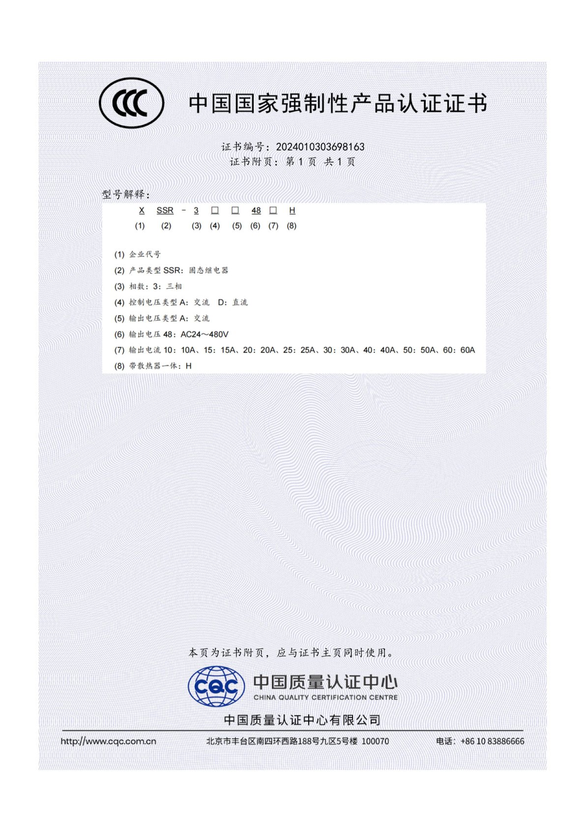
A designer should request the certificate for the exact model under consideration. Certificate scope is model-specific, and a certification held by one model in a family does not automatically extend to every variant. The same applies to testing evidence: the relevant question is not whether a supplier is certified in general, but whether the specific part number being designed in is covered.
SSR Questions Designers Ask Before Committing
What certification should I verify on a solid state relay for consumer electronics?
Verify the certificate for the exact model, not the supplier's general certification list. XURUI holds ISO 9001 quality system certification, and its mainstream products carry CCC, CE, TÜV SÜD, UL, KC and RoHS certification. For the XSSR-3H solid state relay, the CCC certificate is registered as number 2024010303698163 by the China Quality Certification Centre (CQC) under GB/T 14048.5-2017, valid from 30 September 2024 to 29 September 2029. Request the certificate document and confirm that the model you intend to use falls within its scope, because certificates are issued per model and do not automatically transfer across a product family.
What OEM and ODM customization is available on switches and relays?
XURUI operates in both OEM and ODM modes, with customization covering handle design, logo, dimensions and operating characteristics. The engineering team includes more than 24 engineers, and the company holds more than 60 national independent patents. In practice this means a consumer electronics design team can discuss mechanical and dimensional adaptation alongside the electrical specification rather than treating the switch as a fixed off-the-shelf item. Customization discussions should start from confirmed drawings and the actual load conditions, since operating characteristics interact with the load type the device will switch.
What are the minimum order quantity and purchasing terms?
The minimum order quantity is 100 units. Delivery terms are EXW and payment terms are TT. Acceptance is based on pre-shipment test results rather than a self-declared quality statement. For a design team moving from prototype to pilot production, an MOQ at this level allows a realistic validation batch before committing to volume, which is usually the point at which thermal behaviour inside the real enclosure becomes clear.
What can be confirmed at the sample and pre-shipment stage?
Quality control at XURUI is 100% pre-shipment test, meaning each unit is tested before it leaves the facility rather than relying on batch sampling alone. Samples allow the design team to validate the device under the actual load, mounting orientation and enclosure conditions. After-sales support is provided remotely, which matters during the validation phase when questions about wiring, thermal behaviour or load compatibility tend to surface quickly and need an engineering answer rather than a sales one.
What lead time and production capacity should I plan around?
Standard lead time is 15 to 30 days, and monthly capacity ranges from 5,000 to 250,000 units. Export markets served include the EU, Asia-Pacific, North America and the Middle East. For a consumer electronics programme, the practical implication is that pilot quantities and volume ramp sit within the same production system, so the device validated at sample stage is produced on the same line as the volume order. If you are scheduling a design-in around a specific window, it is worth confirming the current lead time against your build plan before locking the part into the BOM — you can send an inquiry to the XURUI team with your load details and target quantities.
Conclusion: Know the Category Before You Specify the Part
A solid state relay is a semiconductor switching device with an optically isolated input and no moving contacts in the current path. It exists because mechanical contacts wear, click, bounce and arc, and because a growing number of consumer products cannot tolerate any of those behaviours. It is not a universal replacement for the electromechanical relay — it brings conduction heat and off-state leakage, and those constraints have to be designed around rather than ignored.
The most useful way to understand the category is to place it correctly within a switch portfolio. Micro switches, limit switches, safety interlock switches, foot switches, toggle switches and reed switches sense or respond to the physical world. The solid state relay acts on the load. A design team that understands which role each component plays will specify both more accurately, and will avoid the common beginner's error of treating the SSR as a drop-in substitute for a mechanical switch rather than a different kind of device altogether.
Next Step: Move From Concept to Specification
This explainer covers the category. The ratings, curves and compliance documents cover the part. If you are ready to evaluate a specific solid state relay for a consumer electronics design, the XURUI product line publishes model-level specifications across the solid state relay range, and the engineering team can review your load, mounting and certification requirements against the actual product data.
Download the full XURUI product catalogue (PDF) for model-level specifications, or contact the team directly at Leon@chinaxurui.com / +86-577-62911448 to discuss a sample request or quotation.
Zhejiang XURUI Electronics Co., Ltd. — NO.3 Yandangshan Road, Wenzhou Bridge Industrial Park, Beibaixiang Town, Yueqing, Wenzhou City, Zhejiang, China. Website: xuruiswitch.com
Have Questions or Need More Details?
Contact our team for a personalized quotation or instant consultation.
Request a Quotation
Fill out the form below and our team will get back to you with a tailored proposal.
WhatsApp Direct Chat
Prefer to chat in real-time? Message us on WhatsApp for instant assistance & quick answers.
- Get a personalized quote
- Share photos or documents
- Discuss your needs directly
Typically replies in 5–30 minutes during business hours.