
How to Choose a Solid State Relay for Inductive Loads: A Technical Guide
A solid state relay (SSR) that switches a resistive heater reliably for years can fail within weeks when the same relay is wired to a motor, a transformer, or a solenoid valve. The relay has not changed — the load has. Inductive loads store energy in a magnetic field and release it every time the current changes, producing inrush current, turn-off voltage transients, and fast voltage edges that can re-trigger the SSR's output thyristor.
Selecting a solid state relay for inductive loads is therefore a different exercise from selecting one for resistive heating. Output current rating, surge capability, dv/dt immunity, switching mode, and in many cases an external snubber network all determine whether the relay survives the first month of service. This guide describes the technical problem first, then gives an eight-step selection procedure that engineers, panel builders, and procurement teams can apply directly. Product references are drawn from the XURUI solid state relay line.
Problem Definition: What an Inductive Load Does to an SSR
An inductive load is any load whose current passes through a winding or coil: AC induction motors, transformer primaries, contactor and relay coils, solenoid valves, compressor windings, and magnetic ballasts. Every one of them behaves differently from a resistive heater, and the difference is not a matter of degree.
Inrush current at energization
When an inductive load is switched on, the current does not rise to its steady-state value in a single step. A motor starting direct-on-line draws a starting current above its rated running current while the rotor accelerates. A transformer energization can produce a brief magnetizing inrush as the core saturates. An SSR rated only for the steady-state load current may see a current well above its rating during the first cycles, and the output thyristor's junction temperature rises in proportion to that current.
Inductive kick at turn-off
At the moment of turn-off, the energy stored in the magnetic field has to go somewhere. The inductor opposes any change in current and generates a voltage transient proportional to the rate at which the current is forced to change. In a resistive circuit that transient is small; in an inductive circuit it can exceed the supply voltage. If the SSR's blocking voltage capability is not respected, the transient forces the device back into conduction or damages it outright.
Phase displacement and dv/dt false triggering
In an inductive circuit the load current lags the supply voltage by the power factor angle. That phase relationship has a direct consequence for SSR switching. A zero-cross SSR turns on when the supply voltage crosses zero — a favourable instant for a resistive load, where voltage and current are in phase, but not necessarily for an inductive load, whose current waveform is shifted relative to the voltage waveform.
The turn-off side is more critical. An SSR's output thyristor stops conducting when its current falls below the holding current. With an inductive load, that zero-current instant does not coincide with a zero-voltage instant; the device must immediately block a substantial voltage while the voltage across it is rising quickly. The rate of rise of that voltage is the dv/dt stress. If dv/dt exceeds what the output device can tolerate, the thyristor re-triggers spontaneously. The result is a loss of control — the relay appears to stay on, switches half-cycles, or operates erratically — even though the device is not shorted.
Industry Background
The solid state relay market is estimated at USD 1.74 billion in 2025 and is projected to reach USD 2.36 billion by 2030 (MarketsandMarkets). Asia-Pacific accounts for an estimated 42% of that market in 2025, driven largely by electric vehicle charger deployment and photovoltaic inverter manufacturing in China and Japan (Mordor Intelligence). Industrial solid state relays are required to comply with international safety standards including IEC/EN 60947-4-3 for contactors and motor-starters, and UL 508 for industrial control equipment (IEC / UL Solutions).
Two structural facts in that data matter for inductive-load selection. First, panel-mount SSR designs held the largest mounting configuration share at 38.67% in 2025, while DIN-rail variants are the fastest-growing segment with a forecast 7.11% CAGR (Mordor Intelligence) — meaning more relays are being installed inside control panels next to motors and transformers, where inductive transients are a daily event. Second, the 0–20 ampere current bracket accounted for 44.13% of the SSR market in 2025 (Mordor Intelligence), so a large share of installed relays are small units with the least thermal margin to absorb an inrush event.
Industry reports list Sensata (Crydom), OMRON, Carlo Gavazzi, Schneider Electric, Panasonic, and TE Connectivity among the major global SSR manufacturers (Market Research Future). Buyers comparing suppliers usually evaluate them on certification coverage, published derating guidance, and how clearly the datasheet states the limits of each series. That last point is where most inductive-load failures begin: a datasheet that lists only a headline current rating, without stating how much of it may be used on an inductive load, invites a design that runs the output device beyond its thermal limit.
Where XURUI fits
Zhejiang Xurui Electronic Co., Ltd. (XURUI) is a manufacturer of low-voltage control switches and solid state relays based in Wenzhou, Zhejiang, China, founded in 2002. The company operates a 5,000+ ㎡ facility with 150 employees, an annual output of 20 million units, and a research and development team of more than 24 engineers. Roughly 40% of production is exported, with main markets in the United States, Germany, Japan, South Korea, Turkey, Belgium, and Egypt. XURUI holds ISO 9001 certification, and its mainstream products carry CCC, CE, TÜV SÜD, UL, KC, and RoHS approvals, backed by more than 60 national independent patents. The company performs 100% inspection before delivery and supports OEM and ODM customisation. Its SSR portfolio is specified with both a resistive and an inductive load current safety factor — the single most useful number in this guide.
Detailed Solution: The Parameters That Decide Inductive Load Performance
1. Output current rating and the inductive safety factor
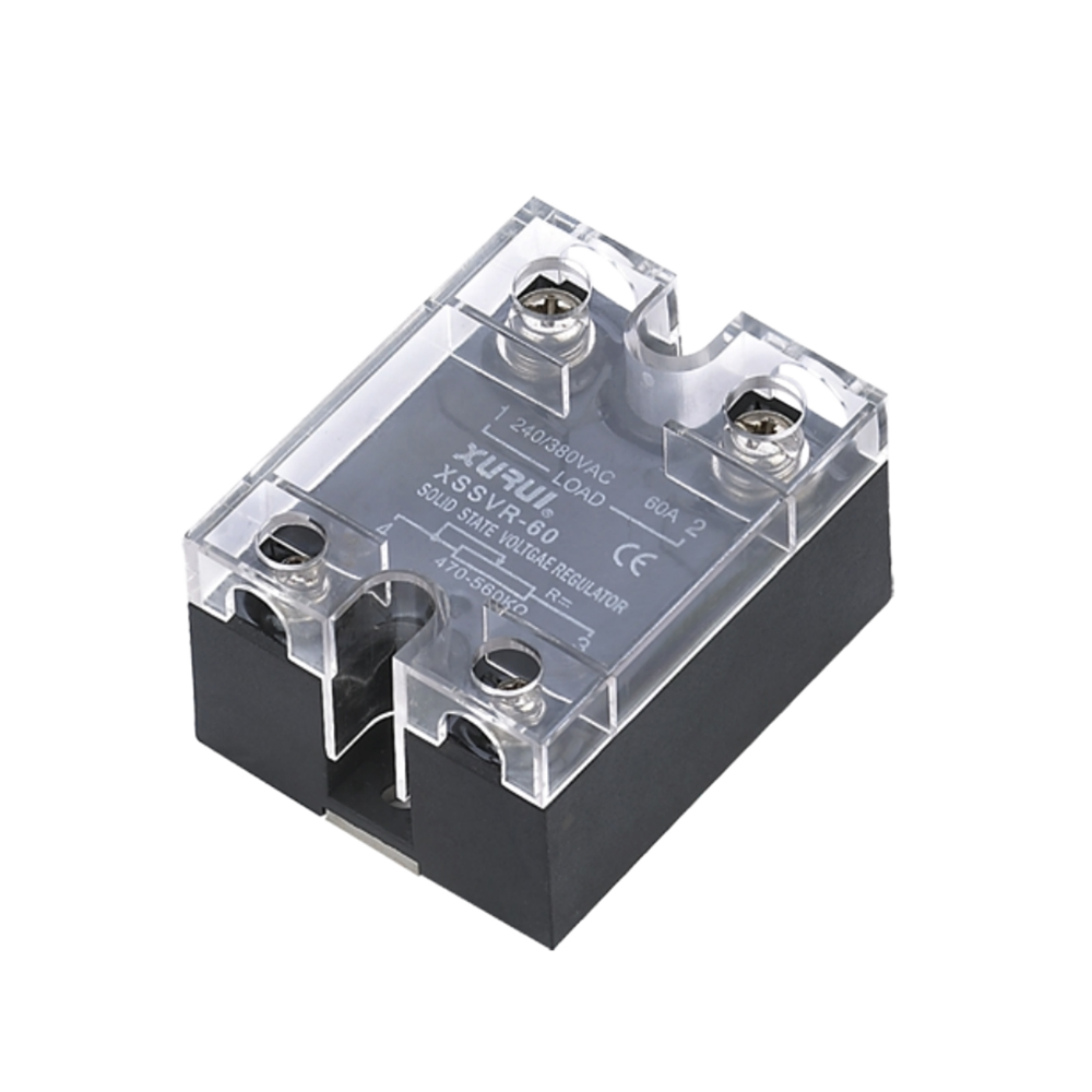
The headline current on an SSR datasheet is not the current the device should carry continuously in every application. XURUI publishes a load current safety factor for its SSR series: 50–60% for resistive loads and 30–40% for inductive loads. This figure appears in the XSSVR-W1/W2, XSSVR-CA W2, XSSVR-VA W2, and XSSR-H specifications.
The practical meaning is straightforward. An SSR whose maximum load current is 40 A should be applied at roughly 12–16 A when it drives an inductive load, versus 20–24 A when it drives a resistive one. The derating covers both the inrush current at energization and the reduced ability of the output device to dissipate heat when the load current is distorted.
2. Surge current capability
Surge capability is what allows an SSR to survive the first few cycles after a motor starts. It is a separate parameter from the continuous current rating and cannot be inferred from it. When a datasheet does not publish a surge figure, the safe engineering response is to increase the current margin rather than assume the device will cope. That is exactly what the 30–40% inductive safety factor does in practice: it converts an unknown surge event into a known continuous margin.
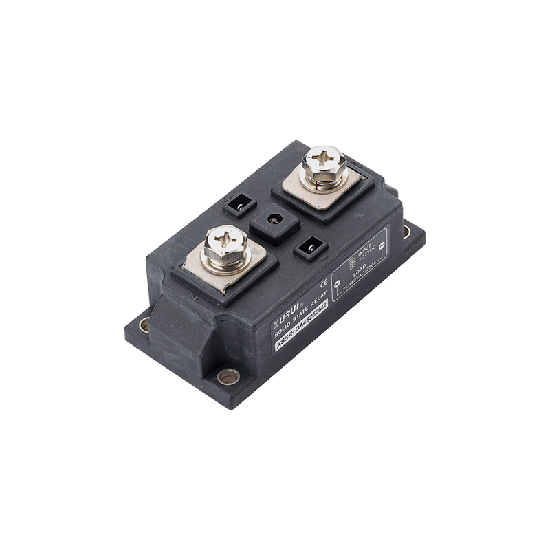
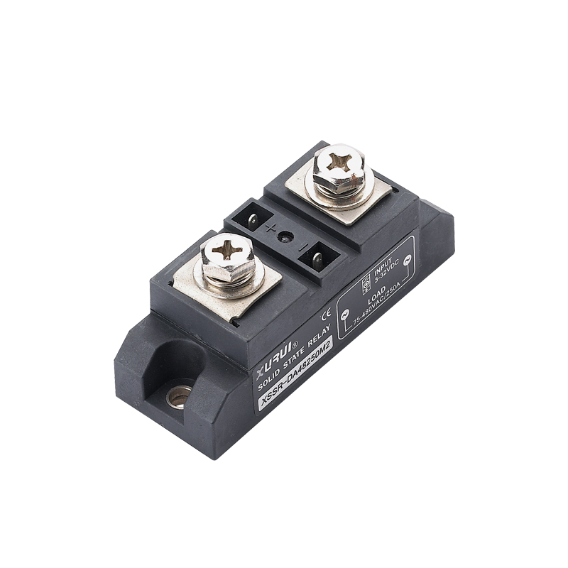
For loads with a severe starting transient, the XSSR-M1 to M6 series is specified with a load current range of 60 A to 1000 A at 75–480 VAC and a zero-crossing trigger method, and is listed for motor control and heating systems as well as general industrial automation. Higher current ratings give proportionally more headroom.
3. dv/dt immunity and transient suppression
dv/dt immunity describes how fast the voltage across an SSR's output can rise after the device has commutated before the output thyristor re-triggers. Because it depends on the device's internal structure rather than on the load alone, the circuit designer has two levers: choose a relay with sufficient intrinsic immunity, and limit the rate of rise seen at the terminals.
An RC snubber network connected across the SSR output is the standard way to limit dv/dt. A metal-oxide varistor (MOV) is often added alongside it, but the two components do different jobs: the varistor clamps the peak of the transient, while the RC network slows the rate of rise. Clamping the peak without limiting dv/dt still leaves the thyristor exposed to re-triggering.
4. Switching mode: zero-cross or phase-angle
An SSR's output switching mode determines at which point in the AC cycle the load is connected and disconnected, and this is where inductive loads differ most from resistive ones.
- Zero-cross switching turns the output on at the voltage zero crossing. The XSSR-M1 to M6 series uses a zero-crossing trigger method. For resistive loads this minimises the switching transient. For inductive loads it limits the initial current step in many circuits, but the phase shift between voltage and current means the switching instant does not align with the load current waveform.
- Phase-angle control varies the conduction angle continuously rather than switching a full half-cycle. XURUI's XSSVR-W1/W2 adjustable series offers a 0–170° conduction angle range, with an external potentiometer as the control input on the W1 and an analogue voltage input on the W2. This mode is used for motor speed regulation, industrial heating, and lighting dimming, where a controlled ramp of applied voltage is preferable to an abrupt full-cycle switch-on.
- Random turn-on (instantaneous switching) is used where the switching instant must be defined by the controller rather than by the mains waveform. The XURUI SSR application range includes zero-cross or random turn-on control, alongside silent operation and high-speed response.
For most inductive loads the choice comes down to whether the application needs abrupt switching (zero-cross) or a controllable output level (phase-angle). A common mis-selection is to install a zero-cross relay on a load that needs a soft ramp, then add external circuitry to compensate.
5. Control input matching
The control side of an SSR must match the driver actually present in the panel. XURUI's SSR series covers the main industrial control interfaces:
- 3–32 VDC logic control with a control current of 6–25 mA (XSSR-W2, XSSR-M1 to M6, XSSR-H, XSSR-3 W4, XSSR-P4/P5/P6)
- 80–250 VAC control input (XSSR-W2, XSSR-H, XSSR-3 W4)
- 4–20 mA analogue current control (XSSVR-CA W2, XSSVR-3P)
- 0–10 VDC / 0–5 VDC analogue voltage control (XSSVR-VA W2, XSSVR-3P)
- External potentiometer control, 470–560 KΩ / 0.5–2 W (XSSVR-W1/W2), or 2–10 KΩ (XSSVR-3P)
A control input mismatch is not a reliability problem — the relay simply will not switch — but it is a frequent cause of returns, particularly when a 4–20 mA loop is used to drive a relay specified for a 0–10 V input.
6. Isolation, dielectric strength, and thermal path
Inductive transients on the load side must not reach the control side. XURUI specifies a medium withstand voltage of ≥2500 VAC and an insulation resistance of ≥100 MΩ across the SSR families discussed here, including the XSSVR-W1/W2, XSSVR-CA W2, XSSVR-VA W2, XSSVR-3P, XSSR-M1 to M6, XSSR-H, and XSSR-P4/P5/P6. Both parameters matter for inductive loads because the turn-off transient appears as a voltage differential between the output and control circuits; isolation is what prevents it from reaching the PLC input.
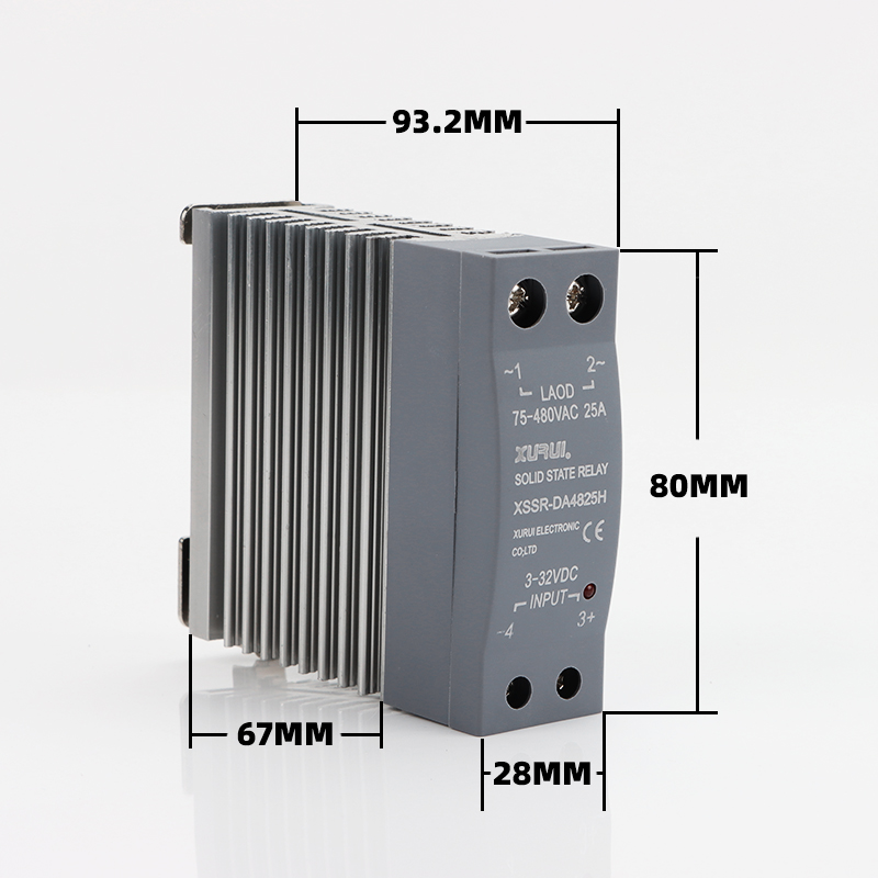
Thermal design is the other half of current derating. The XSSR-H is supplied with an aluminium alloy heat sink, which matters when the relay is mounted in a panel alongside other heat sources. Switching time is specified at ≤10 ms across these series, and the operating temperature range is -20 °C to +70 °C, which sets the boundary for any derating decision.
Step-by-Step Breakdown: Selecting an SSR for an Inductive Load
Step 1 — Characterise the load
Record the steady-state current, the supply voltage, the number of phases, the power factor, and the starting characteristic (direct-on-line motor, transformer energization, or a low-power coil). For a motor, the starting current and acceleration time drive the surge requirement. For a transformer, the energization inrush and the core size determine the transient.
Step 2 — Confirm the load voltage falls inside the SSR's load range
XURUI SSR load voltage ranges start at 24 VAC and extend to 480 VAC depending on the series: 24–480 VAC for the XSSR-H and XSSR-3 W4, 75–480 VAC for the XSSR-W2 and XSSR-M1 to M6, 24–380 VAC for the XSSR-P4/P5/P6, and 0–240 VAC or 0–380 VAC three-phase for the XSSVR analogue and adjustable families. A relay specified for a 0–240 VAC load should not be applied to a 480 VAC circuit, regardless of its current rating.
Step 3 — Apply the inductive derating factor
Take the published maximum load current, multiply by 30–40%, and compare the result with the steady-state load current measured in Step 1. If the derated figure is below the measured current, move up to the next current rating in the series. The derating reference table below shows how this works across the XURUI series that publish both safety factors.
Step 4 — Decide the switching mode
Choose zero-cross switching when the load is switched on and off as a discrete event and the application tolerates full-cycle switching — the XSSR-M1 to M6 series is the zero-cross option with the widest current range. Choose phase-angle control when the application requires a variable output level, such as motor speed regulation or heating control; the XSSVR-W1/W2 series provides that with a 0–170° conduction angle range.
Step 5 — Match the control input to the driver
Confirm whether the controller produces 3–32 VDC logic, 80–250 VAC, 4–20 mA, 0–10 VDC / 0–5 VDC, or a potentiometer resistance. Each corresponds to a specific XURUI series, as listed in the Detailed Solution section above. Pay attention to the guaranteed ON and OFF voltages: the XSSR-3 W4, for example, is specified with a guarantee ON voltage of 3 VDC (DC control) or 80 VAC (AC control), and a guarantee OFF voltage of 1 VDC or 30 VAC.
Step 6 — Assess dv/dt exposure and decide on a snubber
Estimate how fast the voltage across the relay will rise at turn-off, based on the load inductance and the wiring layout. If the transient is significant, add an RC snubber across the output terminals and consider a varistor for peak clamping. Keep the snubber physically close to the relay, and check that its leakage current will not hold a small load in an energised state when the relay is off.
Step 7 — Check isolation and thermal conditions
Verify that the medium withstand voltage (≥2500 VAC across the XURUI series discussed here) and the insulation resistance (≥100 MΩ) are appropriate for the panel environment, and confirm that the ambient temperature stays within the -20 °C to +70 °C operating range. Where the panel is densely packed, prefer a series supplied with a heat sink, such as the XSSR-H with its aluminium alloy heat sink.
Step 8 — Validate with a sample before committing
Inductive loads are difficult to model accurately. Testing a sample on the real load, at the real ambient temperature, is the only way to confirm that the derating and snubber choices are correct. XURUI performs 100% inspection before delivery and supports OEM and ODM customisation, which allows the sample to match the final specification rather than approximate it.
Use Cases: Inductive Loads and Matching XURUI SSR Series
Three-phase motor and CNC equipment
The XSSVR-3P is specified for three-phase loads at 0–380 VAC with a maximum load current of 10–200 A, and is listed for industrial automation including heating, CNC, power supplies, and motor control. Its control input accepts a potentiometer (2–10 KΩ), 0–5 V, 0–10 V, 4–20 mA, or 0–10 mA. Output leakage current is ≤8 mA and switching time is ≤10 ms.
HVAC compressors, fans, and home appliances
The XSSR-H is listed for HVAC systems, home appliances, industrial automation, power control systems, renewable energy, electric vehicles, and medical equipment, with a load current range of 5–60 A at 24–480 VAC and an aluminium alloy heat sink. It is one of the series that publishes both a resistive (50–60%) and an inductive (30–40%) current safety factor.
Industrial heating with transformer-coupled elements
The XSSR-M1 to M6 series covers 60 A to 1000 A at 75–480 VAC with zero-crossing trigger and a modular screw-mount enclosure, and is listed for heating systems, motor control, and industrial automation. The wide current range makes it suitable for high-power heating loads where the transformer or element presents an inductive component. Insulation resistance is ≥100 MΩ and dielectric strength is ≥2500 VAC.
Adjustable-speed drives and controlled dimming
The XSSVR-W1/W2 adjustable series provides phase-angle control with a 0–170° conduction angle range and a load voltage of 0–240/380 VAC or 0–480 VAC. Load current is 10–40 A for the W1 and 50–200 A for the W2. It is listed for industrial heating, lighting dimming, and basic motor speed regulation — the three applications where a variable output level, rather than an on/off switch, is required.
Analogue closed-loop control
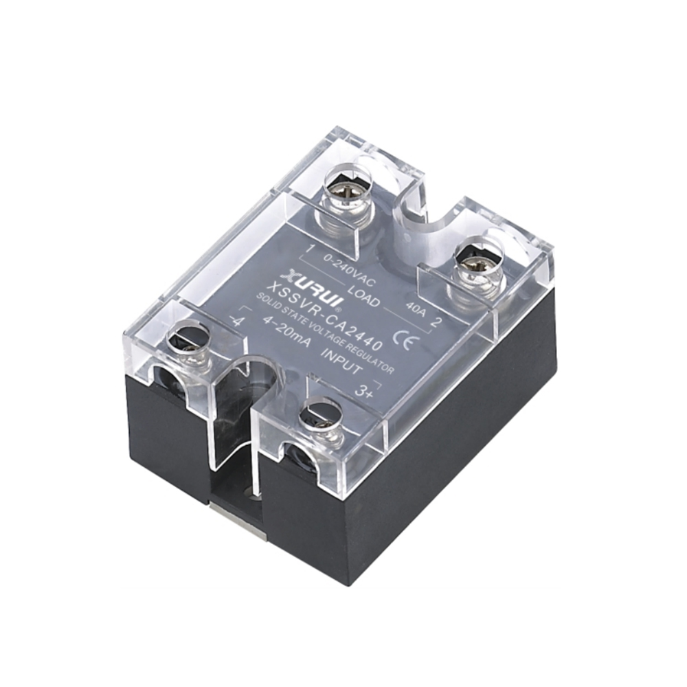
The XSSVR-CA W2 accepts a 4–20 mA control signal and switches 0–240 VAC at 10–120 A, and is listed for analogue closed-loop control in industrial automation systems. The XSSVR-VA W2 performs the same function with a 0–10 VDC or 0–5 VDC input. Both are screw-mounted in a horizontal orientation with reference dimensions of approximately 47.5 × 47 × 33.5 mm.
Small inductive loads: solenoid valves and signal circuits
The XSSR-P4, P5, and P6 models handle a maximum load current of 1 A at 24–380 VAC with a minimum load current of 0.02 A, and are listed for AC motor control as well as heating, street lighting, and traffic signal circuits. Their low minimum load current makes them suitable for low-power coils, where a snubber's leakage current must be checked against the load's holding requirement.
Comparison Table: XURUI SSR Series at a Glance
| Series | Control input | Load voltage | Max load current | Output switching mode | Inductive safety factor |
|---|---|---|---|---|---|
| XSSR-H | 3–32 VDC or 80–250 VAC | 24–480 VAC | 5–60 A | Not specified in datasheet | 30–40% (resistive: 50–60%) |
| XSSR-W2 | 3–32 VDC or 80–250 VAC | 75–480 VAC | 50–200 A | Not specified in datasheet | Not published |
| XSSR-M1 to M6 | 3–32 VDC | 75–480 VAC | 60–1000 A (M1: 60–200 A; M6: 700–1000 A) | Zero crossing | Not published |
| XSSVR-W1 / W2 | External potentiometer (W1) / analogue voltage (W2) | 0–240/380 VAC; 0–480 VAC | 10–40 A (W1); 50–200 A (W2) | Phase angle, 0–170° conduction | 30–40% (resistive: 50–60%) |
| XSSVR-CA W2 | 4–20 mA | 0–240 VAC | 10–120 A | Analogue closed-loop control | 30–40% (resistive: 50–60%) |
| XSSVR-VA W2 | 0–10 VDC / 0–5 VDC | 0–240 VAC | 10–120 A | Analogue voltage control | 30–40% (resistive: 50–60%) |
| XSSVR-3P | Potentiometer 2–10 KΩ; 0–5 V; 0–10 V; 4–20 mA; 0–10 mA | 0–380 VAC (three-phase) | 10–200 A | Not specified in datasheet | Not published |
| XSSR-P4 / P5 / P6 | 3–32 VDC | 24–380 VAC | 1 A | Not specified in datasheet | Not published |
All switching times across these series are specified at ≤10 ms, medium withstand voltage at ≥2500 VAC, insulation resistance at ≥100 MΩ, and operating temperature at -20 °C to +70 °C.
Inductive derating reference table
The values below are calculated from the safety factors published in the XSSVR-W1/W2, XSSVR-CA W2, XSSVR-VA W2, and XSSR-H specifications. They are derived for illustration and are not separate catalogue ratings.
| Series (published max load current) | Resistive application at 50–60% | Inductive application at 30–40% |
|---|---|---|
| XSSVR-W1 (10–40 A) | 20–24 A | 12–16 A |
| XSSR-H (5–60 A) | 30–36 A | 18–24 A |
| XSSVR-CA W2 (10–120 A) | 60–72 A | 36–48 A |
| XSSVR-VA W2 (10–120 A) | 60–72 A | 36–48 A |
FAQ
XURUI holds ISO 9001 certification, and its mainstream products are qualified with CCC, CE, TÜV SÜD, UL, KC, and RoHS approvals. For industrial applications, solid state relays used in motor-starter or contactor roles are typically specified against IEC/EN 60947-4-3 and UL 508 (IEC / UL Solutions). Because certifications apply to specific product families rather than to an entire catalogue, the certificate should be checked against the exact series and rating being purchased.
Yes, provided the current rating is derated for the inductive load. XURUI's XSSR-M1 to M6 series uses a zero-crossing trigger method, covers 60 A to 1000 A at 75–480 VAC, and is listed for motor control, heating systems, and industrial automation. Zero-cross switching does not, however, align with the load current waveform when the power factor is low, so it is not a substitute for phase-angle control where a variable output level is required. For that, the XSSVR-W1/W2 adjustable series provides a 0–170° conduction angle range.
XURUI publishes load current safety factors of 50–60% for resistive loads and 30–40% for inductive loads on the XSSVR-W1/W2, XSSVR-CA W2, XSSVR-VA W2, and XSSR-H series. In practice, an SSR rated for 40 A maximum load current should be applied at approximately 12–16 A with an inductive load. Selecting on steady-state current alone — without applying the inductive factor — is one of the most common causes of field failure in SSR applications.
Sample validation on the actual load is the most reliable way to confirm a selection, because inrush current and dv/dt stress depend on the specific motor, transformer, or coil and on the panel wiring. XURUI supports OEM and ODM customisation and performs 100% inspection before delivery, so a sample can be produced to the intended final specification rather than as a generic unit. Technical questions before sampling can be sent to Leon@chinaxurui.com or discussed on WhatsApp at +86 13968773211.
XURUI has built sales agents and localised service centres in key overseas markets to provide pre-sales consultation, technical support, and after-sales service. Products are exported to the United States, Germany, Japan, South Korea, Turkey, Belgium, and Egypt, among other markets. For a selection review or a quotation on a specific inductive-load application, contact XURUI at Leon@chinaxurui.com, by telephone at +86-577-62911448, or through xuruiswitch.com.
Conclusion
Choosing a solid state relay for an inductive load comes down to three questions that a resistive-load selection never asks: how much extra current will appear at turn-on, how much voltage will appear at turn-off, and how fast that voltage will rise. Answering them means applying an inductive current safety factor rather than the headline rating, matching the output switching mode to whether the application needs an abrupt switch or a controllable ramp, and deciding whether an RC snubber and varistor are needed to keep dv/dt within the relay's capability.
XURUI publishes the numbers needed to do this properly. The 30–40% inductive load current safety factor appears directly in the XSSVR-W1/W2, XSSVR-CA W2, XSSVR-VA W2, and XSSR-H specifications; the XSSR-M1 to M6 series provides zero-crossing switching from 60 A to 1000 A; the XSSVR-3P covers three-phase loads up to 380 VAC and 200 A; and the XSSR-P4/P5/P6 handle small coils down to a 0.02 A minimum load current. Across the range, isolation is specified at ≥2500 VAC medium withstand voltage and ≥100 MΩ insulation resistance, with a switching time of ≤10 ms.
Request a sample for your inductive load
Send the load type, steady-state current, supply voltage, and control signal, and XURUI will recommend the matching SSR series and confirm the derated rating before you order. Samples, OEM and ODM enquiries, and distributor requests are all handled through the same technical contact.
Email: Leon@chinaxurui.com | Tel: +86-577-62911448 | WhatsApp: +86 13968773211
Download the XURUI product brochure (PDF) for full specifications across the switch and solid state relay range.
Zhejiang XURUI Electronics Co., Ltd. — NO.3 Yandangshan Road, Wenzhou Bridge Industrial Park, Beibaixiang Town, Yueqing, Wenzhou City, Zhejiang, China.
Have Questions or Need More Details?
Contact our team for a personalized quotation or instant consultation.
Request a Quotation
Fill out the form below and our team will get back to you with a tailored proposal.
WhatsApp Direct Chat
Prefer to chat in real-time? Message us on WhatsApp for instant assistance & quick answers.
- Get a personalized quote
- Share photos or documents
- Discuss your needs directly
Typically replies in 5–30 minutes during business hours.