
Applying Solid State Relays in Smart Home Automation: Matching Modules to Switching Loads
Why Smart Home Switching Loads Are Harder to Match Than They Look
A smart home system concentrates several problems into one small enclosure: many different load types behind one controller, high switching frequency, no active cooling, and a user who judges the whole system by whether a light comes on. That combination is why load matching matters more in consumer electronics than in a large industrial panel with forced ventilation and generous space.
The constraints that shape every selection decision are consistent across smart home designs:
- Mixed loads on one controller. Lighting, exhaust fans, curtain and blind motors, circulation pumps and small heating elements are often grouped behind the same relay board.
- Frequent, repeated switching. Occupancy automation and scheduling can cycle a relay far more often than a manual wall switch ever would.
- Sealed or unventilated enclosures. Heat generated at the relay has to leave through the enclosure wall, so the thermal path is a design variable, not an afterthought.
- Silent operation as a product requirement. This is one of the practical reasons electronic, non-contact switching is used in these circuits at all.
- Long service expectations. A relay that performs correctly in a laboratory sample and then drifts in year two is a warranty problem rather than a technical one.
Four variables decide whether a match is correct: the load type (resistive, inductive or capacitive input), the continuous load current, the inrush behaviour at switch-on, and the switching frequency the application actually demands.
Industry Background: Where SSRs Sit in Consumer Electronics Today
The demand for SSRs in consumer-facing and smart-building hardware follows the broader market. The global solid-state relay market is estimated at USD 1.74 billion in 2025 and is projected to reach USD 2.36 billion by 2030, according to MarketsandMarkets. Asia-Pacific dominates that market with an estimated 42% share in 2025, driven by electric vehicle charger deployment and photovoltaic inverter manufacturing in China and Japan, according to Mordor Intelligence.
Two figures from the same Mordor Intelligence dataset are especially relevant to smart home hardware. The 0–20 Ampere current rating bracket accounted for 44.13% of the SSR market size in 2025, and panel-mount designs held the largest mounting configuration share at 38.67%, while DIN-rail variants are the fastest-growing segment with a forecast 7.11% CAGR. In other words, the centre of gravity of this market is low-current, compact, easily mounted modules — exactly the segment smart home and consumer electronics designs draw from.
Compliance expectations travel with those modules. Industrial solid state relays are commonly specified against IEC/EN 60947-4-3 (contactors and motor-starters) and UL 508 (industrial control equipment), as described by IEC and UL Solutions. Zhejiang Xurui Electronic Co., Ltd. (XURUI) is a Chinese manufacturer of low-voltage control switches and relays founded in 2002, operating a 5,000+ m² facility with 150 employees, an annual output of 20 million units, and an engineering team of more than 24 engineers. The company holds ISO 9001 quality system certification, and its mainstream products are qualified with CCC, CE, TÜV SÜD, UL, KC and RoHS certification. XURUI's Solid State Relay category is part of a portfolio that also serves household appliances and consumer electronics alongside industrial automation.
The XURUI Solid State Relay Range for Consumer Electronics Projects
XURUI's solid state relay range gives a smart home designer several mounting formats and current classes to work with. Control-side options appear as two suffixes in the model data: DA (3–32 VDC control) and AA (80–250 VAC control). All models in the range share a switching time of ≤10 ms and an operating temperature of −20°C to +70°C.
| Model | Control voltage | Load voltage | Max load current | Mounting / housing |
|---|---|---|---|---|
| XSSR-3 W3 | 3–32 VDC (DA) / 80–250 VAC (AA) | 24–480 VAC | 10–75 A | Horizontal screw mount, PA66 nylon housing |
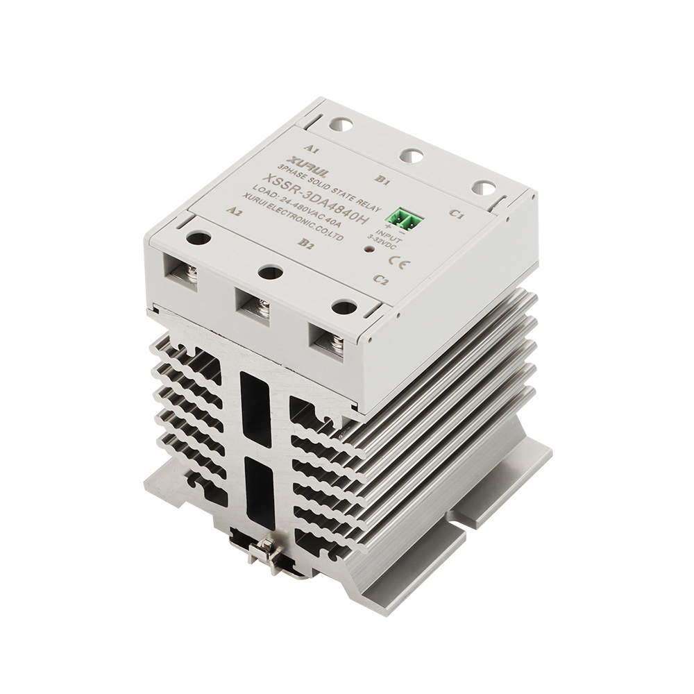
| XSSR-3H | 3–32 VDC (DA) / 80–250 VAC (AA) | 24–480 VAC | 10–60 A | DIN-rail mount, PA66 nylon + aluminium |
| XSSR-F W2 | 3–32 VDC | 24–480 VAC | 10–60 A | Horizontal screw mount, PA66 nylon housing |
| XSSR-H | 3–32 VDC / 80–250 VAC | 24–480 VAC | 5–60 A | Plastic housing, aluminium alloy heat sink |
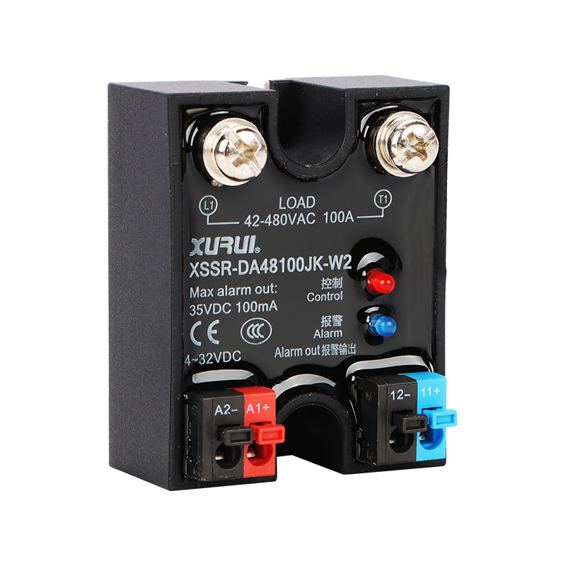
| XSSR-W2-JK | 4–32 VDC | 42–480 VAC | 10–120 A | Plastic housing, aluminium alloy base plate |
| XSSR-W5 | 3–32 VDC | 75–480 VAC | 10–125 A | PA66 nylon housing |
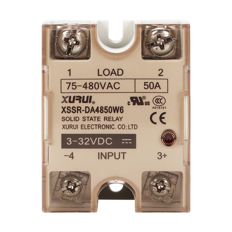
| XSSR-W6 | 3–32 VDC / 80–250 VAC | 75–480 VAC | 10–100 A | PA66 nylon housing |
| XSSR-W15 | 3–32 VDC / 80–250 VAC | 75–480 VAC | 10–200 A | Horizontal bolt mount, PA66 nylon housing |
| XSSR-M1–M6 | 3–32 VDC | 75–480 VAC | 60–1000 A | Screw mount, modular enclosure, zero-crossing trigger |
Model data as published by XURUI. Selection for a smart home circuit should start from the load classification in the next section rather than from the largest available current rating.
Step-by-Step: Matching an SSR to a Smart Home Load
Step 1 — Classify the load before anything else
The load type determines inrush behaviour, and inrush is what usually decides whether a relay survives. Three categories cover most smart home circuits:
- Resistive loads. Heating elements, resistive heating mats and conventional filament lamps. Current follows voltage closely, and the switch-on current is close to the steady-state current.
- Inductive loads. Exhaust fans, circulation pumps, and curtain or blind motors. Current lags voltage, and switching an inductive circuit produces voltages that the relay's output stage has to absorb.
- Capacitive-input loads. LED luminaires and electronic power supplies whose input stage is capacitor-based. These draw a short inrush current while the input capacitor charges, even though the steady-state current is small.
If a smart home panel mixes categories, the correct approach is to treat each output as its own selection problem. One relay rating sized for the largest lighting circuit is not automatically suitable for the fan next to it.
Step 2 — Apply the load current safety factor
This is the step most often skipped. XURUI specifies load current safety factors on the XSSR-H and XSSR-W2-JK series: 50–60% for resistive loads and 30–40% for inductive loads. These figures describe how much of the module's rated current should be used continuously, not how much headroom exists for a transient.
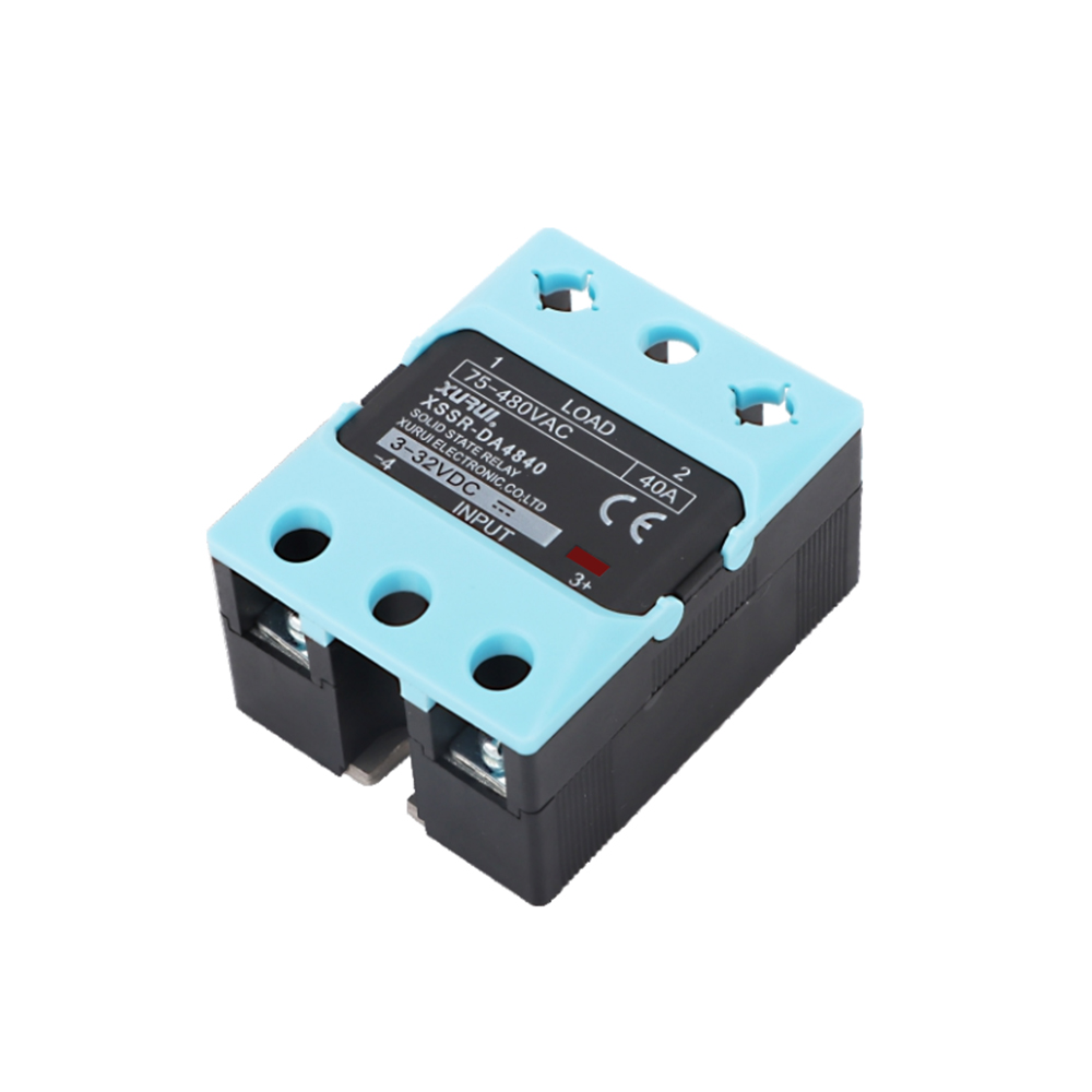
The practical consequence is straightforward. For a resistive lighting circuit drawing 20 A continuously, a 40 A module is planned at roughly 20–24 A — inside the published band. For an inductive load drawing the same 20 A, the 30–40% band means the same 40 A module is planned for roughly 12–16 A, so a larger rating or a different model is required. Sizing an inductive circuit using the resistive factor is one of the most common causes of premature relay failure in consumer hardware.
Step 3 — Confirm control side, load voltage and switching mode
After the current decision, three parameters must line up:
- Control side. Modules with DA control accept 3–32 VDC, which suits the low-voltage DC rails common in smart home controller boards. AA versions accept 80–250 VAC control for mains-side control circuits. The guarantee ON and OFF voltages matter as much as the range: on the XSSR-3 W3, the guaranteed ON voltage is 3 VDC (DA) or 80 VAC (AA), and the guaranteed OFF voltage is 1 VDC or 30 VAC respectively.
- Load voltage window. The range covers 24–480 VAC, 42–480 VAC and 75–480 VAC depending on model. The lower bound is a design limit, not a formality: a module specified from 75 VAC is not intended to switch a low-voltage circuit.
- Switching mode. SSR operation in heating, lighting and motor-control applications is described as electronic, non-contact switching with zero-cross or random turn-on control. Zero-crossing trigger is specified explicitly on the XSSR-M1–M6 series (75–480 VAC, 60–1000 A).
Step 4 — Verify the thermal path and mounting format
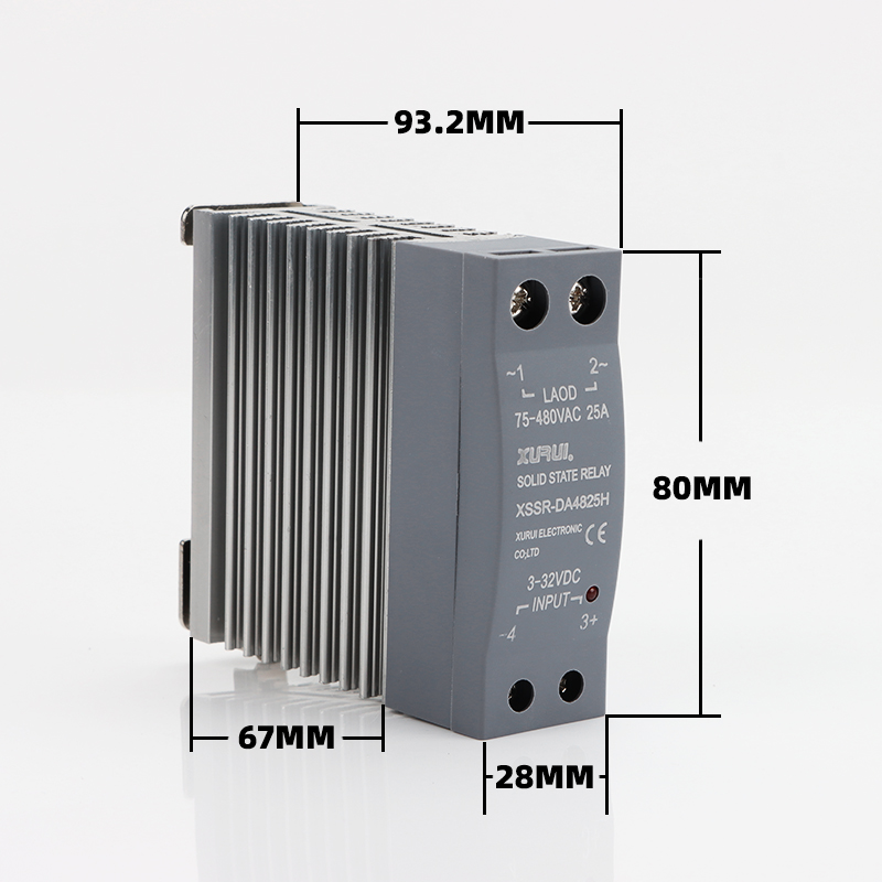
Heat is the second most common reason a correctly rated relay performs poorly. The range offers two practical answers: horizontal screw or bolt mounting on models such as the XSSR-3 W3, XSSR-F W2 and XSSR-W15, and DIN-rail mounting on the XSSR-3H, which integrates the module into a DIN-rail enclosure with a PA66 nylon and aluminium construction. Several models use an aluminium alloy base plate or heat sink to move heat into the mounting surface.
Electrical margins in the range are consistent: dielectric strength of ≥2500 VAC and insulation resistance of ≥100 MΩ on the models documented here. The operating temperature window is −20°C to +70°C, which is important in a smart home because a sealed distribution box can sit well above room temperature when other electronics are active inside it.
One further number deserves attention in low-power smart home circuits. Minimum load current is typically 0.08 A, and 0.05 A on the XSSR-W2-JK. At 230 VAC, a 0.08 A minimum load current corresponds to roughly 18 W. Very low-wattage LED lamps on a single output can therefore sit below the module's reliable switching range, which is a circuit-design issue rather than a relay defect.
Step 5 — Validate with a sample before committing to production
Datasheet matching cannot predict how a specific LED driver or fan motor behaves in a specific enclosure. Sample validation closes that gap. XURUI supports OEM/ODM projects with a minimum order quantity of 100 units, customization covering logo, dimensions and operating characteristics, and 100% pre-shipment testing. Production lead time is 15–30 days, and monthly capacity ranges from 5,000 to 250,000 units depending on the model and configuration.
Limits to Check Before You Commit
An honest matching exercise includes the cases where an SSR may not be the best fit, or where the circuit has to be adapted:
- Standby leakage. Output leakage current is ≤5 mA or ≤8 mA depending on model. In a lighting circuit this can present as a faint glow in some luminaires when the relay is off, and it has to be considered wherever a truly dead circuit is required.
- Very small loads. Minimum load current limits, as described above, can exclude single low-wattage lamps from a switching output.
- Heat removal. If the enclosure cannot move heat away from a screw-mounted module's base plate, a DIN-rail module in a ventilated rail space may be the more realistic choice even when the current rating is identical.
- Load type, not load size. A small inductive motor can be harder on an output stage than a larger resistive heater. The safety factor follows the load type first.
Use Cases: Three Smart Home Circuits and How the Match Changes
Smart lighting circuit
Lighting is the most common smart home output and, on paper, the easiest. A resistive lighting circuit can be planned close to the resistive safety factor band, so a 40 A module comfortably covers a 20–24 A load. The complication arrives with LED luminaires, whose capacitive input stage draws inrush at switch-on while their steady-state current is small. The matching task becomes two-sided: ensure the steady-state current stays above the module's minimum load current, and ensure the module's output stage is appropriate for the driver's inrush behaviour. The XSSR-W5 (10–125 A, 75–480 VAC, 3–32 VDC control) sits in the current class typically used for grouped lighting outputs in consumer electronics hardware.
Motor-driven appliances
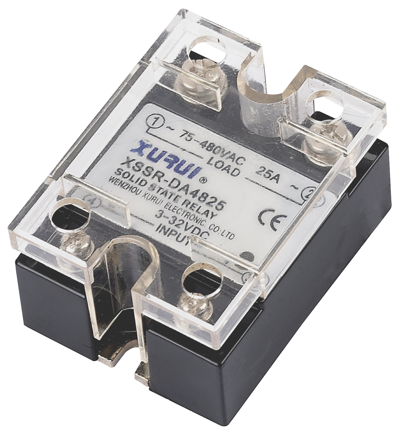
Exhaust fans, circulation pumps and curtain motors are inductive. Here the 30–40% safety factor is the working rule, and the same nominal current that a 40 A module handles comfortably as a resistive load requires a larger module as an inductive one. XURUI's SSR application data lists AC motor control among the intended uses, alongside heating and lighting, and describes the operating mode as silent, non-contact switching with high-speed response.
DIN-rail smart panels
Where a smart home installation uses a distribution board rather than an appliance-mounted board, DIN-rail mounting becomes the practical constraint. The XSSR-3H covers 10–60 A at 24–480 VAC in a DIN-rail format. For higher-current grouped outputs, the XSSR-W15 reaches 10–200 A at 75–480 VAC in a horizontal bolt-mount format with a PA66 nylon housing.
Field experience from adjacent projects shows how these margins translate into service life. An industrial automation solution provider in Malaysia deployed 800 units of the XSSR-M1–M6 series in PLC control and conveyor systems; over a two-year period the reported result was a 65% reduction in maintenance cost with zero major failures. A German industrial equipment manufacturer used 1,200 units of the XSSR-W1 series in heating control systems over three years, with a reported 60% reduction in maintenance cost. Both cases involve switching duty comparable to continuous smart home operation: frequent cycles, enclosed panels, and long service intervals.
Load Type vs. SSR Selection: Comparison Table
| Load type | Typical smart home examples | Behaviour to plan for | What to verify before ordering |
|---|---|---|---|
| Resistive | Heating elements, resistive heating mats, filament lamps | Switch-on current close to steady-state current; current follows voltage | Continuous load held to 50–60% of the module rating (XSSR-H / XSSR-W2-JK published factor) |
| Inductive | Exhaust fans, circulation pumps, curtain and blind motors | Current lags voltage; switching produces transients the output stage must absorb | Continuous load held to 30–40% of the module rating; larger current class for the same nominal amps |
| Capacitive input (driver-based) | LED luminaires, electronic power supplies | Short inrush current at switch-on while the input capacitor charges | That steady-state current stays above the module's minimum load current, and that the switching mode suits the driver's input stage |
Frequently Asked Questions
Do smart home SSRs need UL or IEC certification?
Industrial solid state relays are commonly specified against IEC/EN 60947-4-3 for contactors and motor-starters and UL 508 for industrial control equipment, as described by IEC and UL Solutions. For consumer electronics hardware the certification question is often driven by the end product's target market rather than by the relay alone. XURUI holds ISO 9001 quality system certification, and its mainstream products are qualified with CCC, CE, TÜV SÜD, UL, KC and RoHS certification, which allows a smart home designer to align the relay with the compliance documentation required for the finished device.
Can one SSR model switch both a lighting circuit and a motor-driven appliance in the same smart home panel?
Not at the same current rating. XURUI publishes a load current safety factor of 50–60% for resistive loads and 30–40% for inductive loads on the XSSR-H and XSSR-W2-JK series. A 40 A module can therefore be planned for roughly 20–24 A of resistive load but only roughly 12–16 A of inductive load. A panel that mixes lighting and motor-driven appliances should size each output separately by load type, even when the outputs share the same relay family.
How do I keep SSR cost under control without losing reliability?
Cost in this category is driven mainly by current class, housing and heat-sink construction, mounting format, control-side configuration (3–32 VDC versus 80–250 VAC), and the certification the project requires — not by any single price line. The most effective cost control is correct sizing: oversizing every output to cover the worst-case load type pays for current capacity that is never used, while under-sizing an inductive output creates field failures that cost more than the relay. Applying the derating factor per load type, choosing between a screw-mount model such as the XSSR-3 W3 and a DIN-rail model such as the XSSR-3H based on the enclosure, and confirming the minimum load current suits the smallest lamp on the circuit are all decisions that reduce total cost without reducing reliability.
Can I validate a smart home SSR with a sample before committing to production?
Yes, and for smart home work it is recommended, because LED drivers and small motors vary considerably in switch-on behaviour. XURUI supports OEM/ODM projects with a minimum order quantity of 100 units, customization covering logo, dimensions and operating characteristics, and 100% pre-shipment test on delivered units. A sample build allows the switching behaviour, thermal rise and mounting fit to be confirmed against the actual enclosure before a production order is placed.
What production capacity and lead time can XURUI support for a smart home rollout?
XURUI's stated monthly capacity ranges from 5,000 to 250,000 units depending on model and configuration, with a standard lead time of 15–30 days. The company operates a 5,000+ m² facility with 150 employees and an annual output of 20 million units, exports to markets including the United States, Germany, Japan, South Korea, Turkey, Belgium and Egypt, and provides remote after-sales support. For a project brief, sample request or quotation, the full product catalogue is available here: XURUI product brochure (PDF).
Conclusion: Match the Load First, Then the Module
Smart home automation rewards a specific discipline: classify the load, apply the published derating factor, confirm voltage and control side, verify the thermal path, and validate with a sample. XURUI's Solid State Relay range supports that sequence with DA and AA control options, 24–480 VAC and 75–480 VAC load windows, DIN-rail and screw-mount formats, and current ratings from 5 A to 1000 A, all with ≤10 ms switching time, ≥2500 VAC dielectric strength and a −20°C to +70°C operating window.
Next Step: Sample, Specification or Quotation
Zhejiang Xurui Electronic Co., Ltd. (XURUI) manufactures solid state relays for consumer electronics, home appliances and industrial automation projects, with OEM/ODM customization, a 100-unit minimum order quantity and 15–30 day lead times.
Website: xuruiswitch.com
Email: Leon@chinaxurui.com
Tel: +86-577-62911448 | WhatsApp: +86 13968773211
Address: NO.3 Yandangshan Road, Wenzhou Bridge Industrial Park, Beibaixiang Town, Yueqing, Wenzhou City, Zhejiang, China
Have Questions or Need More Details?
Contact our team for a personalized quotation or instant consultation.
Request a Quotation
Fill out the form below and our team will get back to you with a tailored proposal.
WhatsApp Direct Chat
Prefer to chat in real-time? Message us on WhatsApp for instant assistance & quick answers.
- Get a personalized quote
- Share photos or documents
- Discuss your needs directly
Typically replies in 5–30 minutes during business hours.