
Solid State Relay Explained: How It Works and Why It Matters in Modern Consumer Electronics
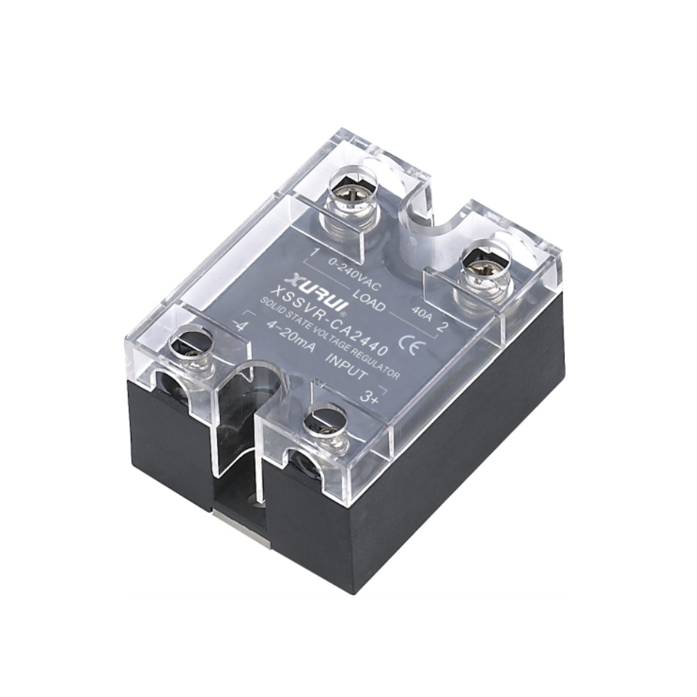
A solid state relay (SSR) is a switching device that opens and closes a load circuit using semiconductor components instead of moving metal contacts. A small control signal drives an input LED, light crosses an optical isolation barrier, and a phototriac, thyristor pair, or MOSFET turns the load on and off. Because nothing physical moves, an SSR switches silently, has no contact wear, and can respond in milliseconds — which is why it has become a standard building block in appliances, thermostats, smart-home modules, and board-level power switching.
The Problem SSRs Were Built to Solve: Contacts That Wear Out
Every electromechanical relay performs the same physical action. A coil pulls an armature, two metal contacts touch, and current flows. That action is well understood and still appropriate for many designs, but it is mechanical, and mechanics have consequences inside a consumer product.
Each time a contact opens an inductive or capacitive load, a small arc forms at the gap. Repeated arcing pits and erodes the contact surface. The armature produces an audible click. The contacts bounce briefly before the circuit settles, so the load sees a burst of make-and-break rather than a clean transition. In a washing machine, a thermostat, or a heater control that switches several times an hour for years, that mechanical action becomes one of the first things a designer has to design around.
A solid state relay removes the moving part entirely. The switching element is a semiconductor, the coupling between control and load is optical, and the transition is governed by the timing of the AC waveform rather than by a spring. The result is a device with no contact erosion, no switching noise, no arc at the gap, and a switching time measured in milliseconds.
Industry Background: A Component Category Moving Toward Modular Switching
Solid state relays are not a niche part. MarketsandMarkets estimated the global solid state relay market at USD 1.65 billion in 2024. Market Research Future reported that panel-mount designs captured approximately 42% of global SSR market share in 2025, while the DIN rail mount segment is projected to grow at a CAGR of 8.0% through 2034.
Those two figures describe different parts of the same picture. Panel-mount formats still carry the largest share because they suit the metal back-plates and heat sinks of machine and appliance control, while DIN-rail formats are growing because control cabinets are increasingly built from modular, snap-on components. For a consumer-electronics design team, the practical reading is that the SSR is no longer only an industrial component: it is a switching option that scales from a small PCB-mount part to a panel-mount block with an aluminium base plate.
The category is also governed by a clear standards map. IEC 62314 is the international standard that specifies requirements for solid-state relays, and EN IEC 62314:2024 is its European publication. IEC 60947-4-3 applies to AC semiconductor controllers and contactors for non-motor loads, a category that includes AC solid state relays used in control gear. In North America, UL 508 is the safety standard for industrial control equipment, under which many solid state relays intended for that market are listed or recognized.
What Is Inside a Solid State Relay
An SSR can be understood as four functional blocks: an input stage, an isolation barrier, an output switch, and a thermal path. Every specification on a datasheet traces back to one of them.
1. The input LED
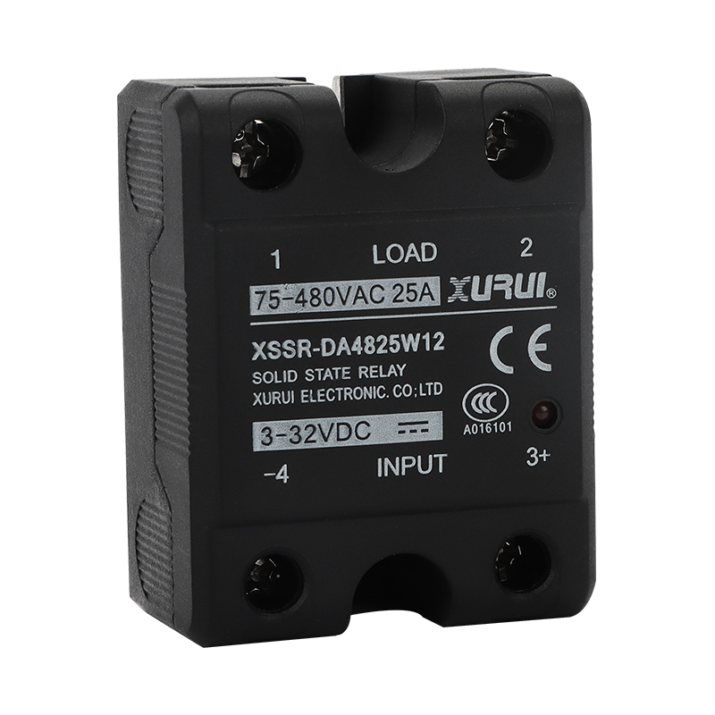
The control side begins with a light-emitting diode. Applying a control voltage — 3–32 VDC on most XURUI DC-input models, 80–250 VAC on AC-input versions, or a 4–20 mA analog signal on the XSSR-CA series — drives a small current through the LED. Datasheet control current is typically 6–25 mA. The LED does no switching itself; its only job is to convert an electrical control signal into light.
2. The optical isolation barrier
The light crosses a transparent insulating layer to a photodetector on the output side. There is no electrical connection between the control circuit and the load circuit, which is the reason a low-voltage logic signal can safely control a mains-level load. The strength of that barrier is expressed as dielectric strength — ≥2500 VAC on the XURUI solid state relay families listed in this article — and is supported by an insulation resistance figure of ≥100 MΩ.
3. The output switch
On the output side the light is converted back into a gate drive. For AC loads, the switching element is normally a phototriac that triggers a pair of antiparallel thyristors, allowing conduction in both half-cycles and natural turn-off at the zero crossing of the load current. For DC loads, the output stage is built around a MOSFET. In both cases the conducting element is a semiconductor junction, not a metal contact.
4. The thermal path and housing
A conducting semiconductor dissipates heat, and that heat has to leave the device. XURUI solid state relays use a PA66 nylon housing, and the higher-current XSSR-W2-JK adds an aluminium alloy base plate to spread heat into a mounting surface. The rated operating temperature for the SSR families described here is −20 °C to +70 °C, which is a device rating, not a guarantee that the part runs cool at full load.
Zero-Cross or Random Turn-On: Two Switching Behaviours
The same hardware can behave in two different ways depending on the output circuit. A zero-crossing SSR waits for the AC waveform to pass near zero volts before it conducts. Turning on at the zero crossing limits the current step into the load, which is why zero-cross models are the usual choice for resistive heaters, lamps, and transformers that dislike abrupt switching. A random turn-on (instantaneous) SSR conducts as soon as the control signal arrives, which is needed where the output must follow a phase-control command or respond without waiting for the next mains zero point.
XURUI describes its solid state relay switching behaviour as non-contact electronic switching with zero-cross or random turn-on control, silent operation, and high-speed response. A buyer specifying an SSR for a consumer appliance should confirm which behaviour the selected model provides, because the two are not interchangeable in a control loop.
How the Switching Sequence Works, Step by Step
- The controller applies a control signal. A thermostat, appliance control board, or PLC outputs 3–32 VDC, 80–250 VAC, or a 4–20 mA analog level, depending on the model.
- The input LED conducts. Control current of roughly 6–25 mA flows through the LED, which emits light proportional to that current.
- Light crosses the isolation barrier. The photodetector on the output side receives the light while remaining electrically separated from the input, maintaining the ≥2500 VAC dielectric barrier.
- The output stage is triggered. On a zero-cross model, the thyristor pair is armed and fires at the next zero crossing of the AC waveform. On a random turn-on model it fires immediately.
- Load current flows. The voltage across the output terminals drops to the breakover (on-state) voltage — ≤2 VAC on most XURUI models, ≤1.5 VAC on the W7, W9 and P series — and the load is energised. Total switching time is ≤10 ms.
- The relay turns off. When the control signal is removed, an AC SSR stops conducting at the next load-current zero crossing, and a small output leakage current of ≤5 mA (≤3 mA on W7 and W9, ≤1 mA on the P series) remains at the load terminals.
Reading a Solid State Relay Datasheet: The Numbers That Matter
Most specification mistakes happen before the part is ever installed, when a buyer reads a headline current rating and skips the conditions around it. Seven figures carry most of the decision weight.
- Control voltage and control current: what the driving circuit must supply. 3–32 VDC is the common DC input window; 80–250 VAC is available where only a mains-level control signal exists.
- Load voltage range: the AC window the output can switch, for example 24–240 VAC, 42–480 VAC, or 75–480 VAC depending on the family.
- Maximum and minimum load current: the upper limit for the semiconductor, and the lower limit below which the output may not hold conduction reliably (0.05 A or 0.08 A on the models listed here).
- Breakover voltage: the on-state voltage drop, ≤2 VAC on most models.
- Output leakage current: what remains at the load terminals in the off state — ≤5 mA on most models.
- Dielectric strength and insulation resistance: the isolation performance, ≥2500 VAC and ≥100 MΩ across these families.
- Load current safety factor: the derating guidance for the load type. XURUI publishes 50–60% for resistive loads and 30–40% for inductive loads.
Why the safety factor matters more than the headline rating. A 40 A solid state relay applied to a resistive heater at a 50–60% safety factor is being used at roughly half its nameplate current. Applied to an inductive load such as a motor or a transformer at 30–40%, the usable current is lower again. Selecting on the nameplate number alone is the most common cause of an SSR running hot in the field.
Where Solid State Relays Appear in Consumer Electronics
The consumer-facing applications of an SSR are rarely labelled as such on the product. The relay is inside the appliance, behind a control panel, or on a board next to the power connector.
Washing machines and laundry appliances
Laundry appliances switch motors, drain pumps, heaters, and valves repeatedly over a long service life. A silent, contact-free switch removes the audible relay click, avoids contact erosion from repeated cycling, and allows the control board to switch a mains-level load from a low-voltage logic signal through the optical barrier.
Thermostats and heating control
Heating control is the classic SSR application: the load is resistive, the switching frequency can be high in a proportional control scheme, and silence matters in a room where the thermostat is mounted. XURUI lists electric stoves, heating and warm-control equipment among the target applications for its AC solid state relays, alongside street lighting, signal lighting, and traffic lighting.
Power adapters and board-level switching
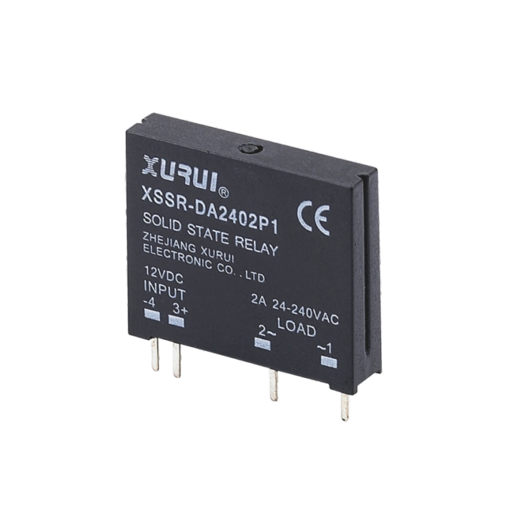
In adapter-class and appliance power products, the same semiconductor switching principle is usually implemented at board level rather than as a DIN-rail module. The XSSR-P series illustrates that format: 24–240 VAC load voltage, load current up to 2 A, 5 V / 12 V / 24 VDC control voltage, ≤1 mA output leakage current, and the same ≥2500 VAC dielectric strength as the larger panel-mount parts.
Smart-home modules and lighting
Smart-home switching modules and lighting controls need a low-voltage control input, a mains-rated output, and no mechanical noise in a bedroom or living space. An SSR satisfies all three, and its zero-cross behaviour is well matched to lamp and heater loads that prefer switching near the AC zero point.

XURUI Solid State Relay Families: Verified Specifications
Zhejiang Xurui Electronic Co., Ltd. (XURUI) is an industrial electric switch manufacturer based in Zhejiang, China, established in 2002, whose portfolio includes micro switches, limit switches, foot switches, toggle switches, reed switches, solid state relays, proximity switches, and photoelectric switches. Its manufacturing facility covers more than 5,000 square metres, employs approximately 150 staff, and reaches an annual production capacity of 20 million units. Solid state relays are manufactured as part of that industrial electric switch portfolio.
The table below compares the XURUI solid state relay families using published model specifications only. It is a family comparison, not a ranking of one model over another: the right part depends on the load, the control source, and the mounting space.
| Model family | Control input | Load voltage | Max load current | On-state / leakage | Switching time | Dielectric strength |
|---|---|---|---|---|---|---|
| XSSR-DA24[]W7 | 3–32 VDC | 24–240 VAC | 5–25 A | ≤1.5 VAC / ≤3 mA | ≤10 ms | ≥2500 VAC |
| XSSR-DA24[]W9 | 3–32 VDC | 24–240 VAC | 5–20 A | ≤1.5 VAC / ≤3 mA | ≤10 ms | ≥2500 VAC |
| XSSR-DA48[]W12 / XSSR-AA48[]W12 | 3–32 VDC or 80–250 VAC | 75–480 VAC | 10–120 A | ≤2 VAC / ≤5 mA | ≤10 ms | ≥2500 VAC |
| XSSR-DA48[]W5 | 3–32 VDC | 75–480 VAC | 10–125 A | ≤1.8 VAC / ≤8 mA | ≤10 ms | ≥2500 VAC |
| XSSR-DA48[]W6 / XSSR-AA48[]W6 | 3–32 VDC or 80–250 VAC | 75–480 VAC | 10–100 A | ≤2 VAC / ≤5 mA | ≤10 ms | ≥2500 VAC |
| XSSR-W2-JK | 4–32 VDC | 42–480 VAC | 10–120 A | ≤1.6 VAC / ≤5 mA | ≤10 ms | ≥2500 VAC |
| XSSR-CA W2 | 4–20 mA analog | 0–240 VAC | 10–120 A | ≤2 VAC / ≤5 mA | ≤10 ms | ≥2500 VAC |
| XSSR-P1 / P2 / P3 | 5 / 12 / 24 VDC | 24–240 VAC | 2 A | ≤1.5 VAC / ≤1 mA | ≤10 ms | ≥2500 VAC |
The families differ in more than current rating. The W2-JK uses a plastic housing with an aluminium alloy base plate for heat spreading. The CA series accepts a 4–20 mA analog input rather than a discrete DC voltage, which suits proportional heating control in analog closed-loop systems. The P series is a compact board-level part with the lowest leakage current in the list, which matters where a load must not glow or hum when the relay is off.
Design Boundaries Buyers Should Check Before Specifying
A solid state relay is not a drop-in replacement for every contactor, and the limits are part of what makes it predictable.
- Heat is continuous, not momentary. The device dissipates power whenever it conducts, so the mounting surface and ventilation are part of the specification, not an afterthought.
- Off does not always mean zero volts. Output leakage current of up to 5 mA remains at the load terminals. Where a load is sensitive to residual voltage, a lower-leakage model or an additional isolation device is needed.
- There is no physical contact gap. Because the output is a semiconductor, the off state is not a mechanical break. Designs that require a visible or physical disconnection need a separate isolating device in the circuit.
- Derating is published, not optional. The 50–60% resistive and 30–40% inductive safety factors exist because inrush and phase angle change the real current through the junction.
- Ambient temperature applies to the whole design. A −20 °C to +70 °C rating describes the device; the temperature inside a closed appliance enclosure may be considerably higher.
Frequently Asked Questions
Which standards and certifications apply to a solid state relay?
IEC 62314 is the international standard that specifies requirements for solid-state relays, and EN IEC 62314:2024 is its European publication. IEC 60947-4-3 applies to AC semiconductor controllers and contactors for non-motor loads. In the United States, UL 508 is the safety standard for industrial control equipment under which many solid state relays are listed or recognized. XURUI holds UL certification under file number E334724 covering toggle switches and solid state relays, and states ISO 9001, CCC, CE, TÜV SÜD, UL, KC and RoHS compliance for its mainstream products. Because a certificate has a defined scope, buyers should confirm that the specific model and rating being purchased falls inside the listed scope rather than assuming it does.
What voltage and current ranges do XURUI solid state relays cover?
The families described in this article span 24–240 VAC and 42–480 VAC and 75–480 VAC load voltage ranges, with load current from 2 A in the board-level XSSR-P series up to 125 A in the XSSR-DA48[]W5. Control options include 3–32 VDC, 4–32 VDC, 80–250 VAC, and a 4–20 mA analog input on the XSSR-CA W2. The 0–240 VAC load window of the CA series makes it the analog-controlled option for proportional heating rather than simple on/off switching.
How does the load type change the rating I should choose?
XURUI publishes load current safety factors of 50–60% for resistive loads and 30–40% for inductive loads. In practice that means a relay rated for a given current should be applied at roughly half that current into a resistive heater, and at a lower level again into a motor or transformer. The minimum load current also matters at the other end of the range: 0.05 A on the W7, W9, W12 and W2-JK families, and 0.03 A on the P series, is the lower bound below which conduction may not be reliable.
How do I request a sample or a quotation for a specific model?
Samples and quotations are handled directly by the manufacturer. XURUI can be reached by email at Leon@chinaxurui.com, by telephone on +86-577-62911448, or by WhatsApp on +86 13968773211, and the company address is NO.3 Yandangshan Road, Wenzhou Bridge Industrial Park, Beibaixiang Town, Yueqing, Wenzhou City, Zhejiang, China. The most useful starting point for a sample discussion is the load voltage, the load current and its type, the available control signal, and the mounting format, because those four inputs determine which family fits. OEM and ODM customisation is supported where a standard model does not match the mechanical or electrical interface.
Conclusion
A solid state relay is a small, well-defined device: an LED converts a control signal into light, an isolation barrier keeps control and load apart, and a semiconductor output switch conducts the load current until the control signal disappears. That architecture removes the two things that limit a mechanical relay — contact wear and switching noise — and replaces them with two things a designer must manage — heat and leakage current.
For consumer electronics, the practical value is straightforward. A washing machine, a thermostat, a smart-home module, or an appliance power stage all need a low-voltage signal to control a mains-level load reliably and quietly over a long service life, and an SSR does that from a 3–32 VDC input with a ≥2500 VAC isolation barrier and ≤10 ms response. The engineering discipline sits in the datasheet: derate for the load type, plan the thermal path, and check the leakage current against the load's sensitivity.
More specification detail on the XURUI solid state relay and switch portfolio is available on the company website at xuruiswitch.com.
Next Step: Match an SSR to Your Appliance Design
If you are evaluating a solid state relay for a consumer device, the fastest route is to send the load voltage, load current and load type, control signal, and mounting space. XURUI will confirm the matching family from the W7, W9, W12, W5, W6, W2-JK, CA and P series, and discuss sample arrangements and OEM/ODM requirements.
Download the catalogue: XURUI product brochure (PDF)
Email: Leon@chinaxurui.com · Tel: +86-577-62911448 · WhatsApp: +86 13968773211

Have Questions or Need More Details?
Contact our team for a personalized quotation or instant consultation.
Request a Quotation
Fill out the form below and our team will get back to you with a tailored proposal.
WhatsApp Direct Chat
Prefer to chat in real-time? Message us on WhatsApp for instant assistance & quick answers.
- Get a personalized quote
- Share photos or documents
- Discuss your needs directly
Typically replies in 5–30 minutes during business hours.