
Solid State Relay Application Guide: What to Use When Designing SSRs into Consumer Electronics
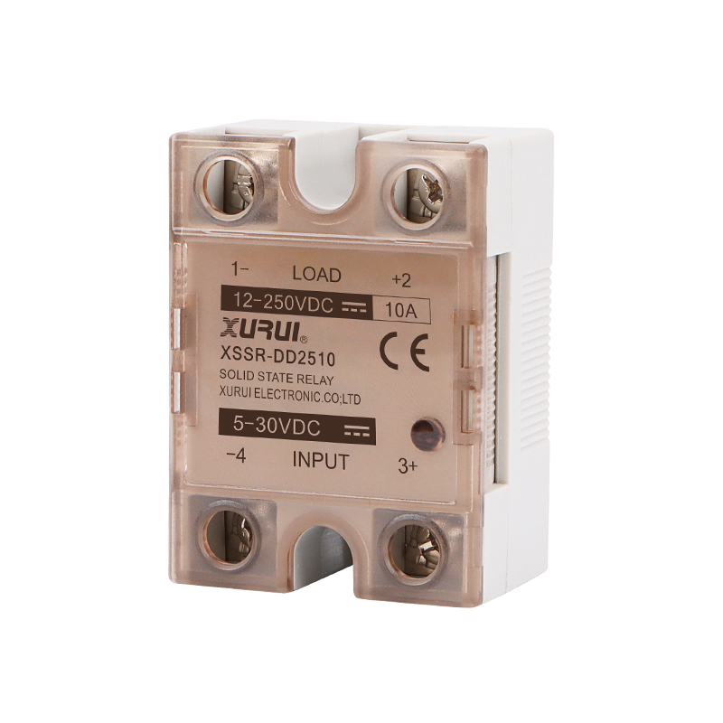
Every consumer-electronics design that switches an AC or DC load eventually reaches the same fork in the road: mechanical relay, or solid state relay? For heating elements, LED lighting drivers, and small motor loads, the solid state relay (SSR) increasingly wins the argument. It has no moving contacts, it switches silently, it tolerates very high cycle counts, and it can be driven straight from a low-voltage logic rail.
What an SSR does not offer is a drop-in substitution. It brings its own constraints. The output stage has to be matched to the load type. The current rating has to be derated. Heat has to go somewhere inside a sealed enclosure. The package has to fit the space that is left. And the part has to sit inside a certification envelope that the end product's compliance team will actually accept.
This guide is organised the way a design engineer works through the problem. It starts with what an SSR is and when it beats a mechanical relay, then walks through the constraints in the order they usually bite — load matching, switching behaviour, current derating, heat, space, and certification — and finishes with the low-voltage control-side components that complete the same design. The focus throughout is application logic and product fit, not headline ratings.
Problem Definition — Why Consumer-Electronics SSR Selection Is a Constraint Problem
The problem is not a shortage of options. Search “solid state relay” and you will find panel-mount blocks, DIN-rail modules, PCB-mount devices, and analog-controlled units in every current class. The problem is that the constraints arrive together and interact.
A consumer-electronics designer has to satisfy at least six constraints at the same time:
- Load compatibility. A resistive heating element draws a predictable current. A small AC motor draws a start-up inrush well above its running current. A capacitive-input LED driver presents a different profile again. An SSR that is comfortable on one load type may be marginal on another.
- Minimum load current. Every SSR has a floor below which it may not switch reliably. XURUI's XSSR-P1/P2/P3 group specifies a minimum load current of 0.03 A, while the XSSR-F W2 specifies 0.08 A. A load that is too small for the chosen output stage is a genuine failure mode, not a theoretical one.
- Thermal dissipation. The output stage dissipates power proportional to the current it carries. In a sealed appliance enclosure with no fan, that heat has nowhere to go. The XSSR-W1 addresses this with an aluminium alloy base plate beneath a plastic housing.
- Space and mounting. A horizontal screw-mounted block with a 59 × 47 × 33.5 mm reference envelope (XSSR-F W2) and a compact P-series module do not occupy the same footprint or cool the same way.
- Control-input compatibility. Consumer products rarely offer 4–20 mA instrumentation loops. Most SSR families accept 3–32 VDC control, but the XSSR-P1/P2/P3 group is offered specifically for 5 V, 12 V, and 24 VDC control inputs.
- Certification and market access. The compliance envelope of the finished product decides which relay variants are acceptable — and this is usually discovered late.
Because these constraints interact — a higher current rating means more heat and often a larger package, which can then fail a space constraint — the efficient approach is to eliminate options in a fixed order, not to compare headline specifications side by side.
Industry Background — Where the SSR Category Stands
The SSR category is established and growing. The global solid-state relay market is estimated at USD 1.74 billion in 2025 and is projected to reach USD 2.36 billion by 2030 (MarketsandMarkets). Asia-Pacific is the dominant region, with an estimated 42% share in 2025, driven by EV charger deployment and photovoltaic inverter manufacturing in China and Japan (Mordor Intelligence).
Two data points from that market are directly useful to a consumer-electronics engineer. First, demand is concentrated at low and mid power: the 0–20 A current rating bracket accounted for 44.13% of the SSR market in 2025 (Mordor Intelligence). Second, mounting format is a live segmentation axis — panel-mount designs held the largest configuration share at 38.67% in 2025, while DIN-rail variants are the fastest-growing segment with a forecasted 7.11% CAGR (Mordor Intelligence).
Compliance is the other structural feature of the category. Industrial solid state relays are required to comply with international safety standards including IEC/EN 60947-4-3 (contactors and motor-starters) and UL 508 (industrial control equipment) (IEC / UL Solutions). Consumer products frequently work to a partially overlapping set of rules, which is exactly why the relay supplier's certificate file is usually the first document a compliance team asks for.
On the supply side, XURUI (Zhejiang Xurui Electronic Co., Ltd.) is a Chinese manufacturer of industrial electric switches and solid state relays, founded in 2002 and based in Wenzhou, Zhejiang. The company runs a 5,000+ ㎡ factory, employs around 150 people, and produces roughly 20 million units per year, with about 40% of output exported to markets including the United States, Germany, Japan, South Korea, Turkey, Belgium, and Egypt. Its SSR range spans the P, F, W and M series, from compact logic-controlled modules up to heavily derated modular blocks.
Detailed Solution — A Load-First Framework for Constraint-Led Selection
The practical way to choose an SSR for a consumer product is to work through the constraints in the order in which they eliminate options.
1. Match the output stage to the load type
Resistive loads — heating elements, resistive lighting — are the easiest case: current is close to sinusoidal and in phase with voltage. Inductive loads, such as small motors and solenoids, shift current behind voltage and can generate turn-off transients. Capacitive-input loads, including many LED drivers, present a high inrush at switch-on.
XURUI publishes explicit derating guidance on its analog-controlled XSSVR-CA W2 and on the TÜV-certified XSSR-W2-JK: a load current safety factor of 50–60% for resistive loads and 30–40% for inductive loads. In practice this means a relay rated at 40 A should be sized against roughly 20–24 A of resistive load and only about 12–16 A of inductive load. This single rule resolves more mis-selection than any other.
2. Choose the switching mode
Zero-crossing output stages turn the load on near the AC zero-voltage point. This reduces inrush and conducted noise, and it suits resistive loads well. XURUI's XSSR-M1~M6 series specifies a zero-crossing trigger method. Where the consumer product needs proportional or closed-loop regulation rather than simple on/off control, an analog-controlled relay is the better fit — the XSSVR-CA W2 accepts a 4–20 mA input and switches a 0–240 VAC load at 10 A to 120 A.
3. Size the current with margin, using the minimum load current as a floor
Two numbers matter on every SSR: the maximum load current and the minimum load current. Across XURUI's range, minimum load currents range from 0.02 A on the XSSR-P4/P5/P6 group and 0.03 A on the XSSR-P1/P2/P3 group, to 0.08 A on the XSSR-F W2, XSSR-W1, and XSSR-W5/W6 models, and 0.05 A on the XSSVR-CA W2. If a consumer product's standby or trickle load falls below that floor, the relay may not switch cleanly.
4. Treat heat as a design output, not an afterthought
The SSR is a heat source. The XSSR-W1 uses an aluminium alloy base plate for heat transfer, and the family operates within a stated range of −20 °C to +70 °C. Inside a sealed enclosure, that base plate has to be given a path to the case or an internal surface. Where the mounting format allows it, panel-mount and screw-mounted designs transfer heat more effectively than a fully enclosed module, because the metal base sits in direct contact with the panel.
5. Check the space and mounting constraint early
Reference dimensions in XURUI's range vary from roughly 47.5 × 47 × 33.5 mm for the horizontal, screw-mounted XSSVR-CA W2, to 59 × 47 × 33.5 mm for the horizontal screw-mounted XSSR-F W2, up to the modular, screw-mounted XSSR-M1~M6 blocks. Settling this constraint before the thermal calculation avoids the common situation of a relay that meets the electrical requirement but cannot be fitted.
6. Verify the certification envelope
For SSRs, XURUI's XSSR-DA48 series holds a TÜV SÜD certificate issued against EN 62314:2006. At company level, XURUI holds ISO 9001 quality system certification, and its mainstream products carry CCC, CE, TÜV SÜD, UL, KC, and RoHS certification. Where a consumer product is destined for a market that recognises industrial control standards, the relevant third-party references in the category are IEC/EN 60947-4-3 and UL 508.
7. Complete the low-voltage control side with matching switches
An SSR only switches what its control signal tells it to. In a consumer device, that signal usually originates from a mechanical actuator — a door interlock, a lid detect, a user toggle, or a magnetic proximity sensor. XURUI manufactures that control layer in the same house:
- Micro Switch XW-16 — rated AC-12 380 VAC 16 A and DC-12 250 VDC 5 A, 1NO + 1NC contact form, IP40, −25 to +80 °C, used in household appliances, machine tools and electromagnets.
- Micro Switch XV-15 (16A) — 16 A / 250 VAC, IP40, with electrical life above 100,000 operations and mechanical life above 1,000,000.
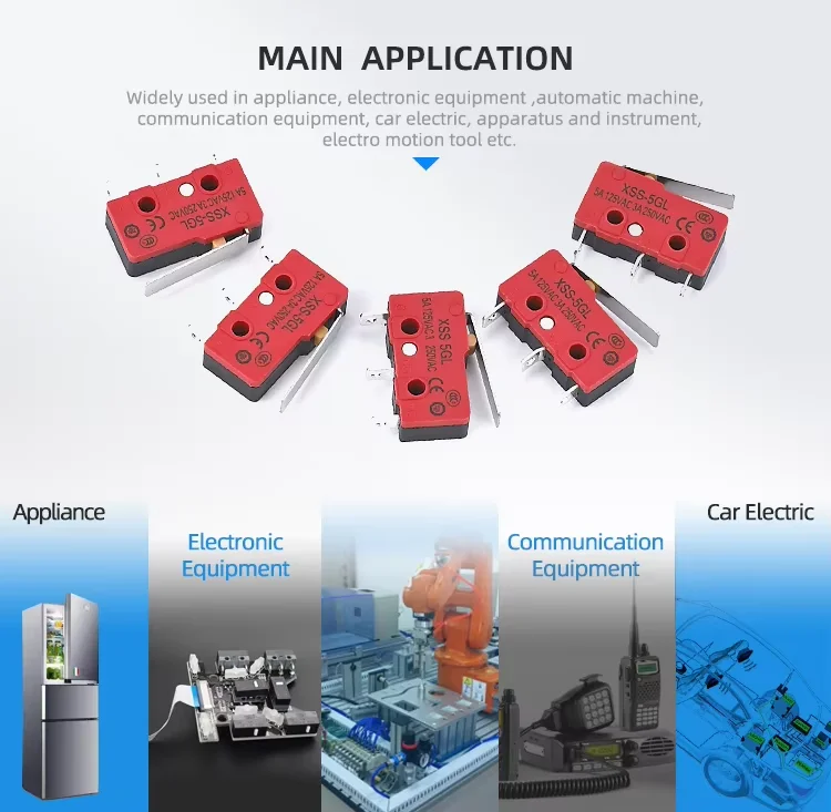
- Micro Switch XMS-5 and XSS-5 — 5 A / 125–250 VAC class devices specified for home appliances, automotive, consumer electronics, industrial automation and medical equipment.
- Limit Switch XZ-93 — AC-15 3 A / 240 VAC and 0.27 A / 250 VDC, IP65, −10 to +70 °C, for mechanical equipment and instruments.
- Limit Switch XZ-8 — 5 A / 250 VAC, IP65, −20 to +60 °C, covered by a UL certificate to UL 508.
- Toggle Switch XT / MTS series — MTS rated 6 A / 125–250 V and XT rated 15 A / 250 VAC and 25 A / 250 VAC, IP40, carrying UL, CCC and KC certification.
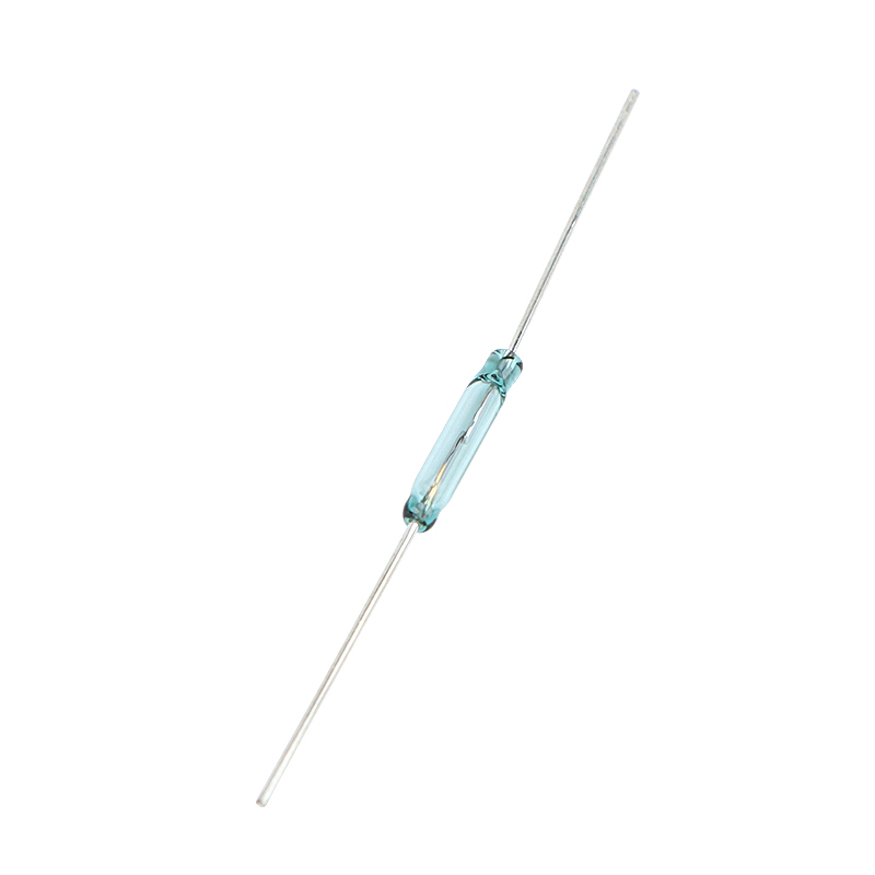
- Reed Switch XGH — 2 × 10 mm to 8 × 50 mm glass-tube construction, contact rating 1 VA to 30 VA, breakover voltage ≥ 100 VDC, −10 to +85 °C, CE marked, used in consumer electronics, home appliances, automotive and security systems.
Sourcing the control-side switches from the same manufacturer shortens the compliance chain, because the certification set is already aligned.
Step-by-Step Breakdown — From Load Definition to Production Release
Step 1 — Define the load, not the relay
Write down the load type (resistive, inductive, capacitive), the steady-state current, the inrush current, the supply voltage, and the duty cycle. For a consumer heater this is usually straightforward. For a motor or an LED driver, the inrush figure is the one that decides the current class.
Step 2 — Select the switching mode
Choose zero-crossing output for resistive loads and for any design sensitive to conducted emissions. Choose an analog-controlled device such as the XSSVR-CA W2 when the product needs proportional regulation rather than simple on/off control.
Step 3 — Apply the safety factor
Take the derived load current and divide by the applicable safety factor — 50–60% for resistive loads and 30–40% for inductive loads, as specified on the XSSVR-CA W2 and the TÜV-certified XSSR-W2-JK. Then confirm the result still sits above the chosen model's minimum load current.
Step 4 — Define the control side
Confirm whether the product can supply 3–32 VDC control, or whether it needs a 5 V, 12 V or 24 VDC variant as offered in the XSSR-P1/P2/P3 group, or an 80–250 VAC control input as offered on the XSSR-W1 and XSSR-W6.
Step 5 — Plan the thermal path
Estimate the dissipated power from the load current, then decide how that heat leaves the relay. A model with an aluminium alloy base plate, such as the XSSR-W1, gives more thermal headroom than a fully plastic-housed module in the same current class.
Step 6 — Fix the mounting and space
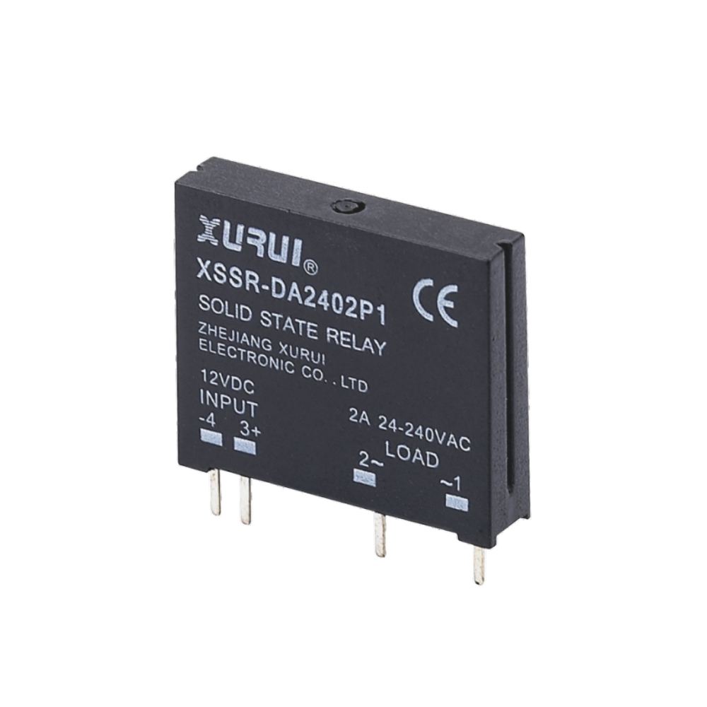
Choose between horizontal screw mounting (XSSR-F W2, XSSVR-CA W2), compact module format (P series — XSSR-DA2402P1, XSSR-DA2402P2/2403P2, XSSR-DA3803P3/3805P3, XSSR-DA3801P4, XSSR-DA3802P5/3803P5, XSSR-DA3805P6) or modular screw mounting (XSSR-M1~M6). Where a three-phase load is involved, the usual approach is one single-phase module per phase, with each module's derating evaluated independently.
Step 7 — Close the compliance file
Collect the certificate set required by the target market. For XURUI SSRs this means the TÜV SÜD certificate to EN 62314:2006 covering the XSSR-DA48 series, plus the company-level ISO 9001, CCC, CE, TÜV SÜD, UL, KC and RoHS documentation that applies across the mainstream range.
Step 8 — Validate with a sample
Run the chosen relay against the real load at the real enclosure ambient. XURUI's production routine includes a 100% pre-shipment test, and the company supports OEM/ODM customization of handle, logo, dimensions and operating characteristics — which is normally what a consumer-electronics project needs once the enclosure geometry is fixed.
Use Cases — Three Consumer-Electronics Load Profiles
Case 1 — Resistive heating elements in countertop appliances
A resistive heater in a countertop appliance is a near-ideal SSR load: current is in phase with voltage, and cycle counts are high enough that contact wear would be the dominant failure mode for a mechanical relay. This is where zero-crossing switching pays off and where derating is simplest to calculate. For loads in the 10–60 A band at 24–480 VAC, the XSSR-F W2 is specified for exactly this application group — heating, lighting, and motor control — with ≤10 ms switching, a 47–63 Hz frequency range, a −20 to +70 °C operating range and a PA66 nylon housing.
Field experience bears this out. In one three-year deployment, a European industrial equipment manufacturer using the XSSR-W1 in heating control systems reported a 60% reduction in maintenance cost, with fewer mechanical failures recorded. The same logic transfers to consumer heating products: the payback of SSR selection shows up in service cost, not in unit price.
Case 2 — LED lighting drivers
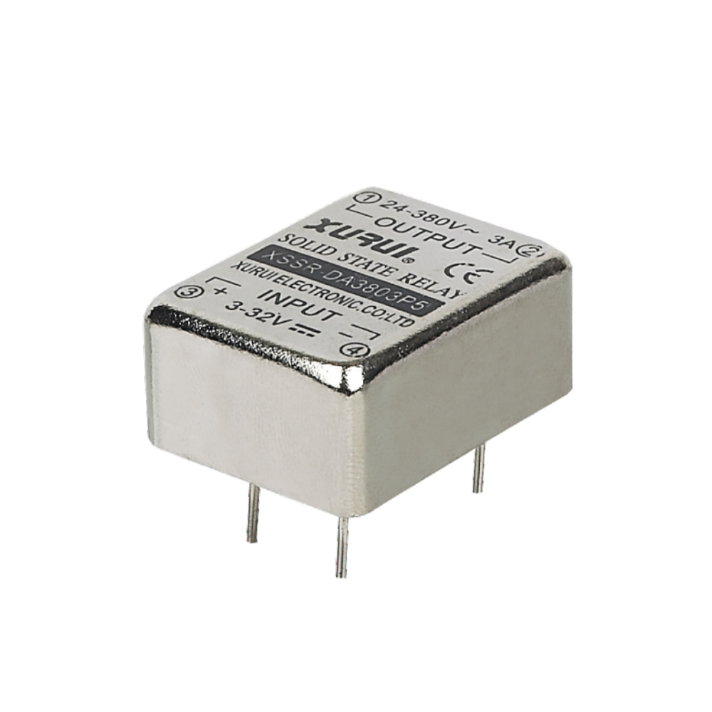
LED driver loads are the least forgiving of the three. A capacitive input draws a high inrush at switch-on, which is why the timing of turn-on matters. Zero-crossing output stages reduce that inrush by closing near the voltage zero point. The XSSR-P4/P5/P6 group (XSSR-DA3801P4, XSSR-DA3802P5/3803P5, XSSR-DA3805P6) is specified for 24–380 VAC loads up to 1 A with a minimum load current of 0.02 A and ≤1 mA output leakage — a fit for low-power lighting control where leakage current itself can cause a faint glow in the lamp.
Case 3 — Small motor loads
Small AC motors — fans, pumps, and similar loads — are inductive. Current lags voltage, turn-off can produce transients, and start-up current exceeds running current. This is the case where derating does the most work: applying the 30–40% inductive safety factor to a nominal current class typically moves the design up one or two rating steps. The XSSR-P1/P2/P3 group is specified for AC motor control at 24–240 VAC with a maximum load current of 2 A and a minimum of 0.03 A, while the XSSR-W1 and XSSR-F W2 extend the same application into higher-current classes.
Comparison Table — XURUI SSR Models by Constraint Profile
| Model | Control input | Load voltage | Max load current | Min load current | Mounting / form | Typical consumer-electronics fit |
|---|---|---|---|---|---|---|
| XSSR-DA2402P1 / 2402P2 / 2403P2 / DA3803P3 / DA3805P3 (P1–P3 group) | 5 V, 12 V, 24 VDC; 6–30 mA | 24–240 VAC | 2 A | 0.03 A | Compact PA66 nylon module | Small motors, low-power switching |
| XSSR-DA3801P4 / DA3802P5 / DA3803P5 / DA3805P6 (P4–P6 group) | 3–32 VDC; 6–25 mA | 24–380 VAC | 1 A | 0.02 A | Compact PA66 nylon module | Signal-level and low-power lighting control |
| XSSR-F W2 | 3–32 VDC; 6–25 mA | 24–480 VAC | 10–60 A | 0.08 A | Horizontal screw mount, PA66 nylon housing | Heating elements, LED drivers, small motors |
| XSSR-W1 | 3–32 VDC / 80–250 VAC | 75–480 VAC | 10–100 A | 0.08 A | Plastic housing + aluminium alloy base plate | Higher-current heating and general switching |
| XSSVR-CA W2 | 4–20 mA analog | 0–240 VAC | 10–120 A | 0.05 A | Horizontal screw mount, PA66 nylon housing | Proportional / closed-loop control |
| XSSR-M1 ~ M6 | 3–32 VDC; 6–25 mA | 75–480 VAC | 60–1000 A (M1: 60–200 A; M6: 700–1000 A) | — | Modular screw mount, zero-crossing trigger | Above typical consumer scale |
Every model above is specified with ≥2500 VAC dielectric strength, ≤10 ms switching time and an operating temperature range of −20 °C to +70 °C. The XSSR-DA48 series is covered by a TÜV SÜD certificate issued against EN 62314:2006.
FAQ
What certifications should a solid state relay carry for a consumer-electronics product?
The answer depends on the target market, but the supplier's certificate file resolves it fastest. XURUI's XSSR-DA48 series holds a TÜV SÜD certificate issued against EN 62314:2006. At company level, XURUI holds ISO 9001 quality system certification, and its mainstream products carry CCC, CE, TÜV SÜD, UL, KC and RoHS certification. In the wider category, the recognised industrial references are IEC/EN 60947-4-3 for contactors and motor-starters and UL 508 for industrial control equipment. Confirm which of these the end product's test house will accept before locking the relay choice.
Can a solid state relay be customized for a specific consumer-electronics design?
Yes. XURUI supports both OEM and ODM engagement, with customization covering handle, logo, dimensions and operating characteristics — useful when a consumer product's enclosure or actuation geometry is already fixed. Production capacity runs from 5,000 to 250,000 units per month, supported by a 5,000+ ㎡ factory, roughly 150 employees, an annual output of around 20 million units and an engineering team of more than 24 engineers. The SSR range itself spans 3–32 VDC and 80–250 VAC control inputs, 24 VAC to 480 VAC load voltages, and load currents from a 0.02 A minimum on the compact P series up to 1,000 A on the XSSR-M6.
What drives the cost of a solid state relay in a consumer-electronics bill of materials?
The main cost drivers are the output current rating, the control-input type (simple DC logic versus an analog input such as 4–20 mA), whether the design requires an aluminium alloy base plate for heat dissipation, the certification scope needed for the target market, and any OEM/ODM customization. Two relays with similar headline ratings can land at different total costs once derating, heat sinking and compliance testing are included. XURUI's MOQ for customized switch and relay work starts at 100 units.
How is an SSR sample validated before a consumer product moves into production?
Sampling is where two things get confirmed: that the chosen output stage actually switches the real load at the real ambient, and that the thermal path matches the enclosure. Ask for the sample in the exact control-input variant and current rating the design intends to use, because minimum load current, control current and switching behaviour differ across the P, F, W and M series. XURUI's production routine includes a 100% pre-shipment test, and production lead time runs 15–30 days.
What lead time should be planned for SSR volume orders?
XURUI quotes a production lead time of 15–30 days against a monthly capacity range of 5,000 to 250,000 units. For a consumer-electronics programme, read that against the company's 40% export ratio and its established markets — the United States, Germany, Japan, South Korea, Turkey, Belgium and Egypt — which indicates the export documentation and logistics chain is already in place for these destinations. To start a sample request, quotation or distributor discussion, contact XURUI directly.
Conclusion
Consumer-electronics SSR selection is a constraint-elimination exercise, not a specification comparison. Match the output stage to the load, apply the resistive or inductive safety factor, respect the minimum load current floor, design the thermal path before the enclosure is frozen, fit the package to the space that remains, and close the certification file early. Done in that order, most SSR mis-selection disappears.
XURUI manufactures solid state relays across the P, F, W and M series alongside the control-side Micro Switch, Limit Switch, Toggle Switch and Reed Switch families that feed them — which means the electrical and mechanical halves of a consumer switching design can be sourced and certified together. Review the full range in the brochure, or contact the team for a sample matched to your load.
Request an SSR sample or specification quotation
Send your load type, supply voltage, current class and target market, and the XURUI engineering team will match a solid state relay and control-side switch set to your consumer-electronics design.
Visit xuruiswitch.comDownload Product Brochure
Zhejiang Xurui Electronic Co., Ltd.
Email: Leon@chinaxurui.com | Tel: +86-577-62911448 | WhatsApp: +86 13968773211
Address: NO.3 Yandangshan Road, Wenzhou Bridge Industrial Park, Beibaixiang Town, Yueqing, Wenzhou City, Zhejiang, China
Product data referenced in this article is drawn from XURUI's published solid state relay and switch specifications. Market figures are attributed to their respective sources (MarketsandMarkets, Mordor Intelligence, IEC / UL Solutions). Compliance requirements should be confirmed with the relevant certification body for each target market.
Have Questions or Need More Details?
Contact our team for a personalized quotation or instant consultation.
Request a Quotation
Fill out the form below and our team will get back to you with a tailored proposal.
WhatsApp Direct Chat
Prefer to chat in real-time? Message us on WhatsApp for instant assistance & quick answers.
- Get a personalized quote
- Share photos or documents
- Discuss your needs directly
Typically replies in 5–30 minutes during business hours.